Introduction
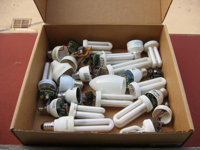
Compact fluorescent lamps have some benefits in comparison with classic light bulbs. It is lower power consumption (to 80%) and much longer lifetime (5 to 15 times). Disadvantages are longer starts mainly at more expensive types, impossibility to use darker and price.
Fluorescent lamps are available usually in these color temperatures:
- Warm white (2700K)
- Cool white (4000K)
- Daylight (6000K)
Most often we meet with "warm white", which is close to classic bulb and which is most pleasant to people.
Compact fluorescent lamp use vacuum pipe similar to classic strip lamp and princip of energy transformation to light is same. Tube has on both ends two electrodes faced with Barium. Kathode has high temperature about 900 degree Celsius and generates many electrons which are accelerated by voltage between electrodes and hits atoms of Argon and Mercury. There arise low temperature plasm. Overflowing energy mercury radiate in a UV light form. Inner side of tube is faced with luminophore, which transform UV light in to the visible light. Tube is powered by alternating current, so that function of electrodes (cathode and anode) is still changing. Because there are used switched converter, which works on tens of kilohertz, that CFL lamp doesn't "blink" in comparison to classic strip tube lamp. Converter, which is present in a screw cap, substitute classic ballast with a starter.
Electrical construction
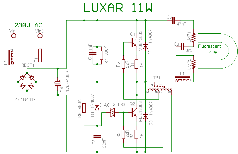
Princip of function we explain on a LUXAR 11W lamp.
Circuit contains supply section, which includes interference suppressor L2, fuse F1, bridge rectifier from 1N4007 diodes and filtering capacitor C4.
Starting section includes D1, C2, R6 and diac.
D2, D3, R1, R3 have protect function.
Other parts have normal operation function.
Lamp start
R6, C2 and DIAC mades first pulse to base of transistor Q2 and cause his opening. After start is this section blocked by diode D1. After every opening of Q2 is discharged C2. There is not possible to collect enough energy for reopening of diac. Next are transistors excitated over very small transformer TR1. It consists of ferrite ring with three windings (5 to 10 coils).
Now are filaments powered over capacitor C3 from voltage rises from resonant circuit from L1, TR1, C3 and C6. Than the tube lights up is resonation frequency specified by capacity of C3, because he has much lower capacity than C6. In this moment is voltage on a C3 over 600V in a relation to used tube. During start is peak collector current about 3 to 5 times bigger than during normal operation. When the tube is damaged, there are hazard of transistor destroying.
Normal operation
When the gas is ionisated in a pipe, C3 will be practically shorted and thanks to this frequency goes down and changer is now drived only by C6 and changer generates much lower voltage but enough to keep the light on.
In a normal situation, when transistor opens, that current to TR1 increasing until his core is saturated and next his feedback to base drop away and transistor closes. Now opens second transistor which is excitated by reversly connected windind of TR1 and all process repeats.
To be continued …