Spehro Pefhany
Microcontroller port pins can typically be driven either high or low, or else be put into an "input" or high-impedance state. This circuit uses the three states to drive two separate LEDs with one port pin. This can be very useful when there are no port pins to spare—something that usually happens.
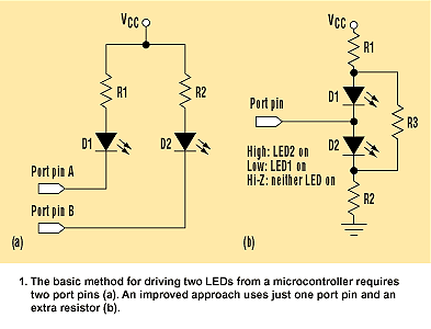
The simple way to drive two LEDs is via two port pins (Fig. 1a). The improved version requires only one additional resistor (Fig. 1b). It can be designed for most reasonable LED voltages and supply voltages, as well as to yield the desired "on" currents in each LED, which may be different if desired. The design parameters are:
V1 = off voltage for D1 (worst case maximum voltage for no visible light from D1)
V2 = off voltage for D2 (worst case maximum voltage for no visible light from D2)
V3 = on voltage for D1 (forward voltage of D1 at design current plus port voltage drop)
V4 = on voltage for D2 (forward voltage of D2 at design current plus port voltage drop)
Ion1 = desired on current for D1
Ion2 = desired on current for D2
Vcc = supply voltage
The design equations are:
Ion1 = [(Vcc − V3)/R1] − [V3/(R2 + R3)]
Ion2 = [(Vcc− V4)/R2] − [V4/(R1 + R3)]
(V1 + V2)/R3 = (Vcc − V1 − V2)/(R1 + R2)
To minimize current consumption, R3 is made as large as possible, without the LEDs turning on with the port pin in the high-impedance state.
These equations can be solved by using an Excel spreadsheet (Fig. 2). This minimizes the sum of the squares of the errors of each LED's on current, as compared to the design values. Inserting typical values as follows, assume one yellow and one red LED for D1 and D2, respectively:
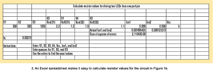
V1 = 1.2 V
V2 = 1.1 V
V3 = 2.2 V (inclusive of port-pin voltage drop when sourcing current)
V4 = 1.9 V (inclusive of port-pin voltage drop when sinking current)
Ion1 = 0.008 A
Ion2 = 0.008 A
Vcc = 5.0 V
The solver tool comes up with values that can be rounded to the closest 5% standard resistance values as follows:
R1 = 300 Ω
R2 = 330 Ω
R3 = 1.2 kΩ
Then, the practical resistor values can be plugged into the same cells that the solver modified, to read the resulting currents and quiescent current, Iq. In this case, the circuit draws a quiescent current of 2.7 mA when both LEDs are off. When it's on, the circuit supplies almost exactly 8 mA to each LED. If it's desired to have both LEDs appear on, the port pin can be rapidly cycled between 0 V and Vcc. If the rate is somewhere around 100 Hz or higher, both LEDs will appear steadily illuminated.
This circuit works best with microcontrollers that have Schmitt-trigger or analog inputs. Other types may draw unnecessary supply current if the input is biased close to the center of the supply voltage.