Miguel A. Vallejo
After visiting some web pages about 2.4 GHz ISM band spectrum analyzers based on the CYWM6935 module, I tried to build my own analyzer, but with some improvements. The references I found on the net used the parallel port or a serial link to a host computer. I want the analyzer to be portable, and easy to transport, so I will use a microcontroller and a graphical LCD.
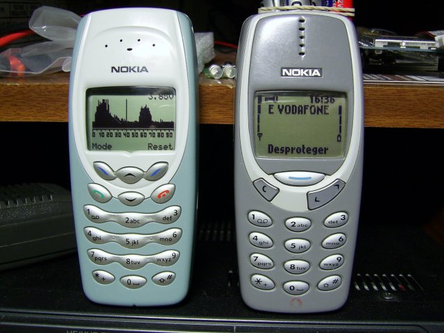
I had also some old Nokia phones, so maybe I can use phone plastic box and build in LCD to make my own portable analyzer, but... Does it can be done? Let's see:
Microcontroller: The microcontroller would be an ATMega8 running at 3.3 volts because both the the LCD module and the CYWM6935 are 3.3 volts devices. The ATMega8 will do nicely the job even running with low internal clock rates, so I choose to run it at 4 MHz using the internal oscillator.
LCD: The LCD would be the one from the phone, in this case a Nokia 3410. The LCD uses a PCD8544, so it must be easy to work with it. There are many code around to use this kind of LCD controllers.
Battery: This phones can use two kind of batteries: Li-ion and Ni-Mh, but both types are equivalent from the equipment's point of view. Useful voltage range is 4.2 down to 3.6 volts. My first idea was to use a voltage regulator to 3.3 volts, but I didn´t find a suitable one, so I choose to put a single 1N4004 diode between the battery and the circuit. The useful range (4.2 down to 3.6 volts) minus the 0.6 volts drop out at the diode will be seen as 3.6 down to 3.0 volts at the circuit supply. The LCD and CYWM6935 module can work from 2.7 up to 3.6 volts, so everything must work safely.
The prototype
I mounted a prototype to test module and microntroller functions when I found my first problem. According to the info on Internet, Nokia's 3410 LCD uses a PCD8544 controller, the same as the Nokia 3310 LCD, so both LCD can be driven with the same firmware. Yes and no. Both LCD use the same PCD8544 instructions set, but screen resolutions are different. Original Nokia 3310 LCD is 84 × 48 pixels, but Nokia's 3410 LCD is 96 × 65 pixels, so LCD routines must be rewritten to use the new resolution.
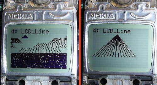
After rewriting the routines, you must expect a working LCD, isn't it? Not again. The Nokia 3410 LCD have a visible resolution of 96 x 65 pixels, but the real resolution inside the LCD controller is 102 × 72 pixels, so you must to have this in mind while writing your code.
 |
|
| Left: Nokia 3410 LCD with Nokia 3310 routines | Right: Nokia 3410 LCD with correct resolution routines |
The second problem was the CYWM6935 module. Timings and a correct module initialization is very important for optimum performance, so once everything was OK, I saw my first 2.4 GHz spectrum display with my test signal: A wireless camera working on 2468 MHz.
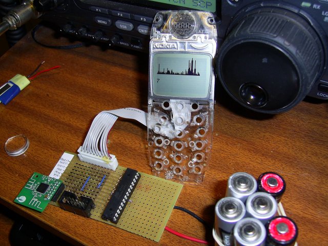
The prototype showing a wireless camera at 2468 MHz
After many tests, I found the different ways to show the spectrum in the display, one to display fast digital signals (like wifi, bluetooth, etc), one to display analog signals (wireless cameras, wireless phones, etc) and one to show a average use of the whole band. To switch easily between these modes I will need a pair of buttons, and because working with batteries, an on screen voltmeter would be nice. This can be easily accomplished with microcontroller's ADC, so the final schematics for the portable 2.4 GHz spectrum analyzer is finished.
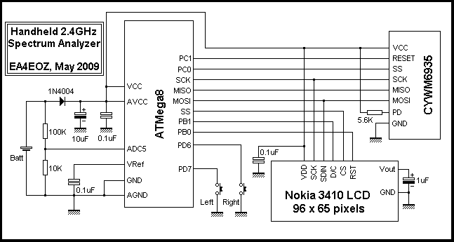
Handheld 2.4 GHz spectrum analyzer schematics
Mounting the analyzer
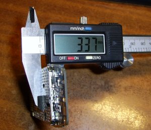
A Nokia 3410 case has a lot of space to mount components, but with one important limitation: You can not go higher that 3.3 millimeter, the height of the original Nokia PCB, so SMD components will help you to accomplish this.
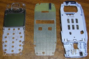
To keep my components under 3.3 millimeter high, I needed to make holes in the PCB to accommodate the PDIP ATMega8 microcontroller and the two buttons. Once the holes are made, I glued together the PCB with the LCD plastic case, in this way I could solder the tiny LCD contacts to the pads with wire.
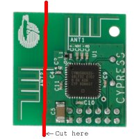
The CYWM6935 module is well above the 3.3mm limit, but it can be placed at the phone's antenna place if previously you cut the module to strip off the transmission antenna: It will not be used.
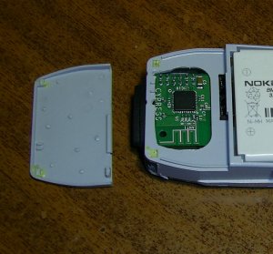
Once every component is in place, I made the connections with thin insulated wire. This is the final result, not beautiful, but fully functional:
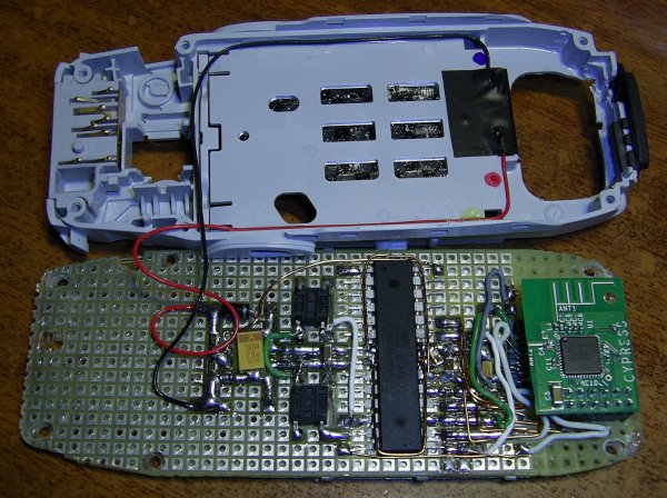
The next step was to place the six screws, so the analyzer was finished.
To be continued