Have you ever tried to repair anything in your car? Have you tried to debug your original circuit? If yes, then you are sure to have a device called multimeter. Usually this thing is about half a kilo heavy and you would normally have to hold it with your both hands. However, it is a very useful and sometimes indispensable device. Working with it everyday, you might have dreamt that one day it could be at least half as heavy. So what would you say if you had a multimeter that is no bigger than a pencil and resembles a little electronic thermometer?
In a nutshell, what I offer is a hand-held device that is used to measure DC voltage within the range of ±50 Volts. Have you ever held a digital medical thermometer in your hand? This pocket shape perfectly suits voltage measurement, especially if you like small microchip design. And how about automatic power down if the process of measurement is interrupted for more than 1 minute? One more practical feature is a sound short-circuit detector onboard; this is required when checking wires and bulbs.
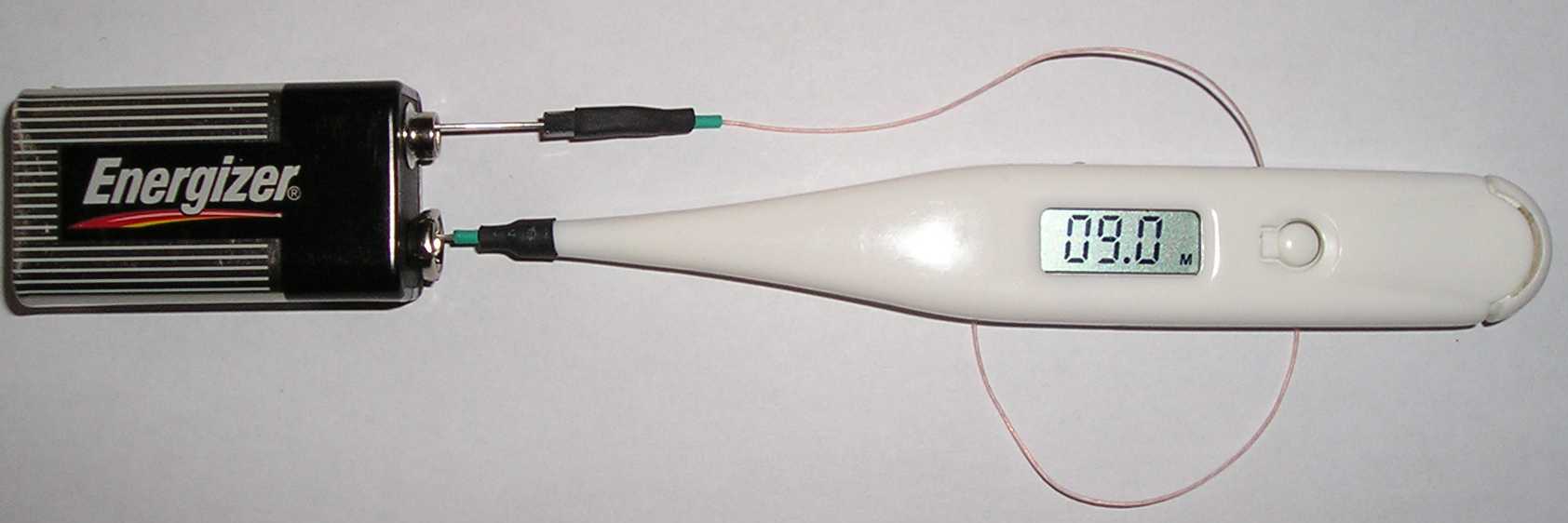
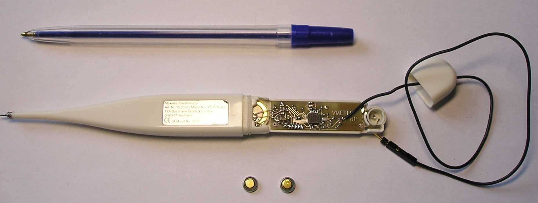
So if you want to get your dream device, go to the nearest drugstore and buy the cheapest digital medical thermometer and change the PCB inside. Now the only thing you need is 1 chip from Atmel – Atmega8L-8MI – very small and cheap but with great potential.
Finally, such a multimeter is an essential device for repairing cars, household appliances, debugging and adjusting electronic circuits. Powering is only 2 alkaline micro cells (watch size). No need to change the battery too often because power consumption is very low (only 300uA), especially in the power down mode (less than 300nA). It is both practical and convenient.
The code was written in IAR Embedded Workbench version 2.31E.
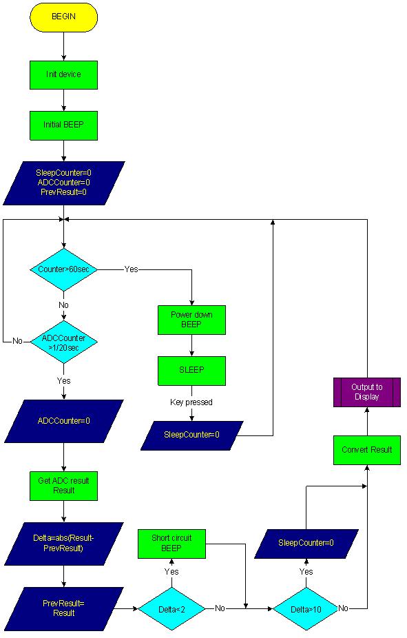
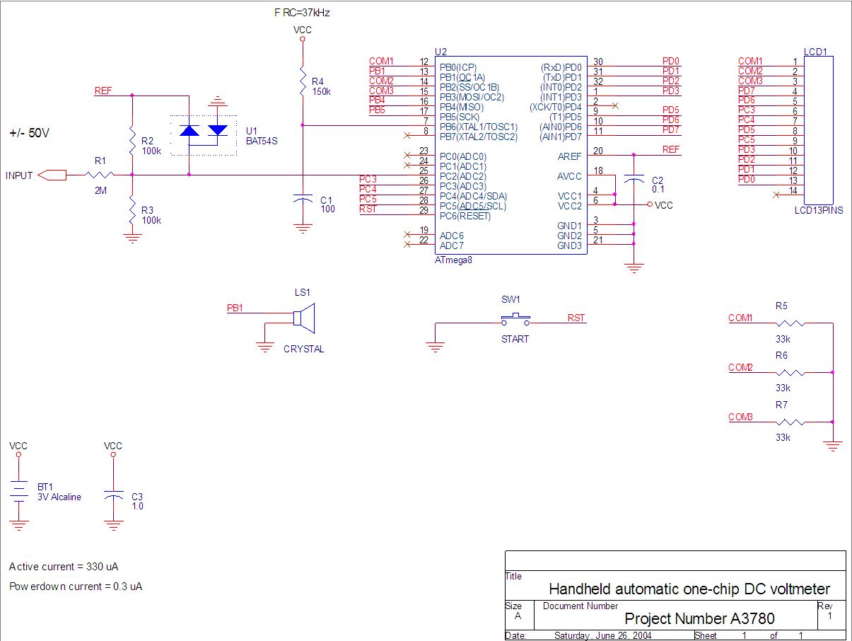
After the Reset procedure (applying power for the first time or after pressing the reset button), the AVR processor initializes TIMER0 and TIMER1. The TIMER0 is configured for timebase and LCD refreshing routine. The 37 kHz RC oscillator (R4-C1) is divided down to 150 Hz for the LCD refreshing interrupt routine by prescaler and TIMER0. The TIMER1 is configured as a PWM generator for sounds (beeps). It beeps twice after the Reset procedure and sounds if the short circuit has been detected.
The ADC works in a 10-bit mode and the ADC procedure is called from the main routine each 50 mSec. The LCD refresh routine is called every 1/150 Sec. The Interrupt procedure generates special succession on the LCD pins for the LCD refreshing. On the pins COM1, COM2, COM3, the AVR processor forms the three level voltage sequences using the R5, R6, R7 resistors in combination with internal pull up resistors (these resistances should be equal) and switching the output and input mode for each COM pin every refreshing period.
The input measuring voltage goes to the internal ADC through the input divider R1-R3 and voltage overprotected diode U1.
Source Code (IAR Embedded Workbench v.2.31E)- download