This project describes the implementation of a phone line audio and event recorder originally devised for monitoring technical support call center attendants for quality assurance purposes.
Our initial objective was to have a device that digitizes the calls with good audio quality and sent the data to a computer for storage and later retrieval. However, we also wanted the recording process to be reliable even in face of power failures or computer crashes, so we expanded our objectives to make it a standalone appliance that could work in cooperation with, but not dependent from, a main computer. That’s why we decided to design and build our own device instead of just plugging a voice modem to the PC: we wanted it to be a truly “plug it in and forget” device.
On the other hand, that meant we were going to reimplement most of a voice modem’s features and add a few of our own, such as a large memory card to store the audio when the PC is not paying attention and a battery backup system. Therefore, our device can be seen as a template for a reasonably generic AVR-based telephony platform that can be easily adapted for other applications, such as an answering machine/interactive voice response system; or, doing away with the LCD and SD/MMC card, it could become a low speed modem; or, adding a few relays, it could become a remote home automation system. It wouldn’t surprise us if our device, sans its privacy-preserving features, gets used by law enforcement or private detectives for their own purposes.
As always, cost is a factor: we wanted our device to be as affordable as possible, which meant avoiding uncommon, specialized or expensive components. It had to be easy to build, within reach of electronics hobbyists such as ourselves. Atmel’s ATMega32 and ATTiny45 MCUs, with their low cost, excellent performance and wide availability of programming tools were perfect for the task.
Features
- Works both as a standalone device or in conjunction with a PC
- Records up to 230 calls or 17 hours of audio with a 512MB MMC/SD card
- DTMF detection for European-style incoming caller ID and outgoing number detection
- Allows listening to calls in real time or replaying them later
- Supports simultaneous record and playback
- Transmits audio over the serial port either in real time or replaying from the memory card
- LCD for call progress monitoring and timing
- Optional “mini-UPS” battery backup allows operation even in case of power failures
Hardware Design
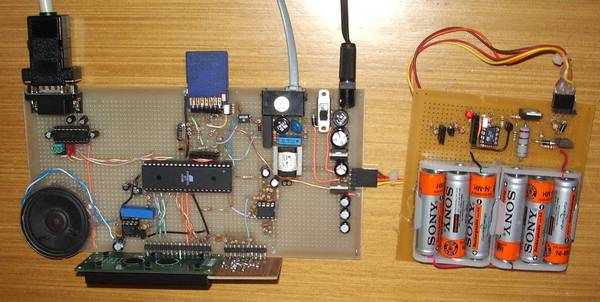
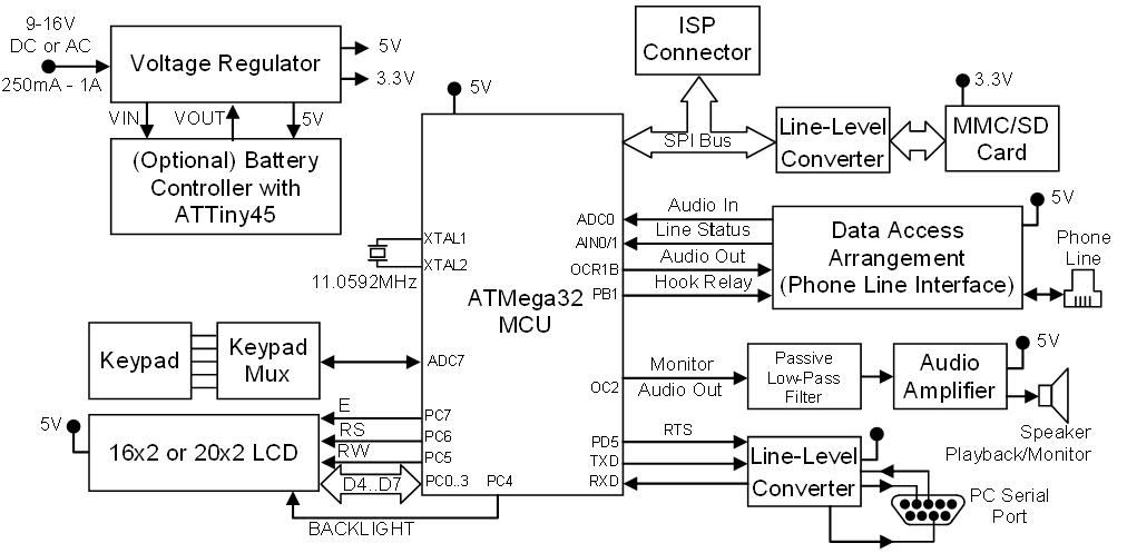
Arguably, the hardware can be described as an integration of several classical circuits available in the literature. The block diagram below shows its major components and their interconnections from a higher level perspective. It is interesting to correlate it with the full schematics and with the assembled device photograph.
Power Subsystem
The voltage regulator provides a 5V rail for most of the system and also 3.3V for the SD/MMC card. It connects directly to the optional battery controller, sporting an ATTiny45 to measure battery voltage and control an LM317-based constant-current source to charge the AAA NiMH batteries. Power switchover is implemented in hardware with a simple transistor arrangement with some diodes to prevent reverse current flows; we feared that implementing switchover in software might be slow enough to brownout the main MCU or the memory card. With this arrangement, however simple it might be, we never had a switchover failure.
We could have had the battery charger integrated with the main MCU instead of using a separate one as we did. However, since in this case we’d have only one ADC, we’d have to perform “sample stealing” – break audio sampling cycle to measure the battery and main voltages. Although that wouldn’t be that big a deal – stealing two samples every second would have no noticeable effect on the audio quality – we preferred the modular approach because we (and our readers) could reuse the battery backup system for other projects. On the other hand, not everyone might want or need the battery backup system.
The ATTiny45 runs with its internal calibrated oscillator at 8MHz, but the software sets the clock prescaler to divide it by four, so the core runs at 2MHz. Two voltage divider resistor networks scale the main and battery voltages from 0-16V to the 0-5V needed by the ADC. PB0 is connected to a transistor that pulls the LM317’s adjust pin to ground whenever it is turned on – and a pull-up makes it on by default. The result is that when PB0 is 1, the constant-current source is off; when we pull it to 0, the constant-current source charges the battery.
The charging current is regulated by the 3.3 Ohm power resistor and it’s about 500mA. Bear in mind that it is quite normal for the LM317 and the resistor to heat considerably when charging, up to the point of being uncomfortable to touch them. However, with those values a heatsink is not necessary. If you decrease the resistor to 2.2 Ohm, on the other hand, a heatsink becomes a necessity. Reducing the resistor even further to 1 Ohm (yielding a 1.25A charging current) might be too much for the TO-92 version of the LM317; in this case, we recommend using the TO-3 version and appropriate heatsinking.
The charger has a level converter and a connector for attaching a serial port for debugging and a led that blinks in tandem with the charging process to provide visual feedback it’s working. They can be safely omitted if so desired.
Main MCU and Clocking Options
The main MCU is an ATMega32 running at 11.0592MHz with an external crystal, important to make the software-based real time clock (used for timestamping the phone calls) decently accurate. Being an exact multiple of the 115,200 bps we need for serial transmission/reception (data is exchanged at slightly more than 8Kbytes/sec) minimizes transmission problems.
The photograph denounces a small sin: when we were assembling the prototype, the only ATMega32 MCU we had at hand was the low-power “L” version, which is rated only up to 8MHz. We were unable to make all the features fit at this speed (although we do suspect it would be possible with more aggressive optimizations) on time for the contest deadline, so we went the overclocking road. The chip took it pretty well: we’ve been running the device at this speed for several weeks and we had no glitches or instabilities. This was a minor issue, however: non-“L” versions are rated up to 16MHz anyway. We’ve ordered non-L versions but we feared they might not arrive in time, which in fact happened.
If you don’t want the SD/MMC subsystem, 7.3728MHz will be fine – and you could even use a smaller MCU, such as ATMega8 or ATMega16.
Using 8MHz is fine too, but you’ll get a -3.6% error in the serial data rate, which makes serial transmission less reliable. So, if you want serial transmission, it’s best to use multiples of 1.8432MHz.
If you don’t care that much for serial reliability and don’t mind the clock drift (say, your PC-side software does the timekeeping or keeps resetting the clock), you can omit the crystal altogether and use the on-chip calibrated RC oscillator.
On the other hand, if you want the SD/MMC support, you do need an MCU with at least 2KB of memory, which makes the ATMega32 the minimum for this project.
We use Timer/Counter0’s CTC mode to divide the main clock by 1,382.4 to give the 8 KHz audio sampling rate. The division by a non-integral factor is performed by having OCR0 set to 172 most of the time but reduced to 171 every five samples (with the prescaler = CLK/8).
Schematic diagram
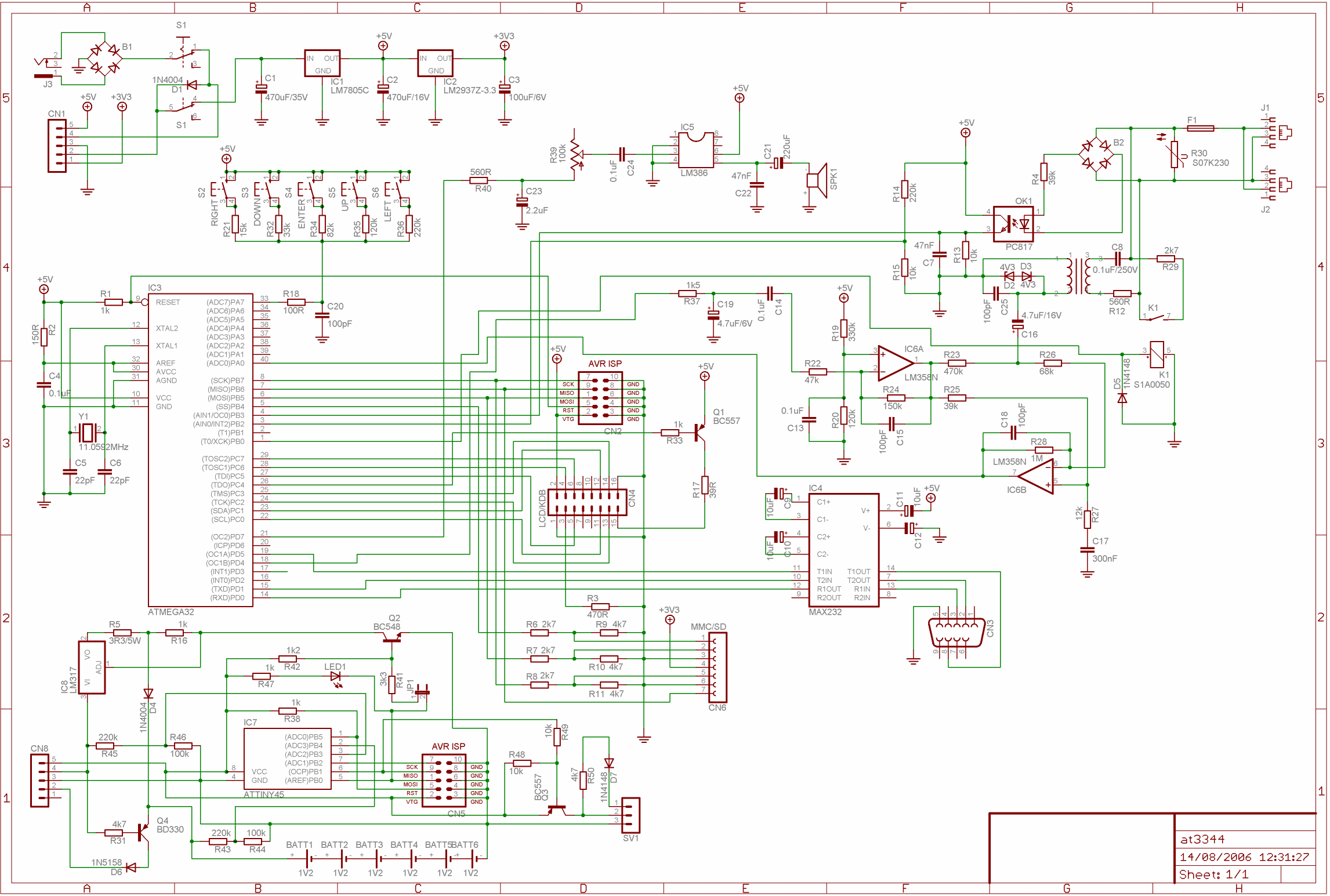
Click to enlarge
User Interface
The HD47780-compatible LCD is nearly directly connected to Port C, using 4-bit transmission mode to save a few pins. A transistor provides a current boost to control the LCD backlight.
For the keypad, we used the capacitor charge timing method to have all the switches use only one of the MCU’s digital pins. The keyboard scan routine first configures the pin as output and sets it to low, bringing it to ground and forcing the capacitor to discharge. Then it reconfigures the pin as input and measures the time until it changes state. Another advantage of this scheme is that it makes easy to upgrade the keypad later, say, to have more keys – it can be treated as a separate hardware unit.
We also have an audio playback port, made with Timer2’s PWM features. After going through an overly exaggerated RC low pass filter, it is sent to an LM386 audio amplifier and to the speaker.
Serial Transmission
The serial line level converter is just a classic MAX232 IC and its following capacitors. We use hardware flow control to keep the computer from sending data faster than we can consume, since we have limited RAM for the receive FIFO. In the assembled device, we added a few jumpers to the serial signals. This is because we planned to add a USB-to-serial converter later on.
MMC/SD Card Interface
Given that MMC/SD cards support the SPI protocol, connecting it to the MCU’s SPI bus is the obvious choice – the native SDCard bus/protocol is way too complicated for our needs and would be overkill anyway.
The line level converter card is just a resistor-based voltage divider for the Chip Select, DataIn and SCK signals. The DataOut is connected directly to the MCU’s MISO pin – the digital input Schmitt trigger does a fine job of understanding the 3.3V as digital 1.
Although there is no explicit support for hot insertion or removal, it kinda works – but we’re not testing this too much, for we are unsure this won’t eventually damage the card or something up.
We were astonished to discover how hard to find MMC/SD connectors were in our local electronics shops, so perhaps the reader will forgive us for the ugly improvisation with the pinhead connector.
Phone Line Interface
The phone line interface is based on Joe Randolph’s “Low Cost Telephone Line Interface DAA, FXO” application note [3] with some changes of our own to allow monitoring the line even when idle – and which probably have made it non-CTR21-compliant. A decoupling 600 Ohm transformer “extracts” the audio from the phone line. Then a pair of operational amplifiers separate incoming and outgoing signals, amplify the incoming audio and provide a 1.28V DC bias, since we use the MCU’s 2.56V voltage reference to circumvent the fact that the LM324 won’t go rail to rail.
Line status detection is performed by an optocoupler in a voltage divider resistor network in tandem with ATMega32’s voltage comparator. When the line is disconnected, we have 0 volts. When the line is connected, we have either ~0.45 volts if it’s in the off-hook state or almost 5V if it is on-hook. So if we have a digital 1, it is “on hook”; otherwise, we use the voltage comparator to discriminate between the two possible digital zero states.
We can seize the line using a reed relay and a resistor just after the protection fuse and varistor, allowing ups to take incoming calls or originate calls as well. This functionality isn’t necessary in a phone recorder, but brings us closer to the idea of making it a generic AVR-based telephony device. Besides, having the device answer calls and turn other devices on/off via relays is one of the cool things we’d like to try next.
The outgoing audio is generated using Timer1’s PWM features. It is fed through a passive RC low pass filter and sent to the op aforementioned separation amps. More work is needed on the balance, though: even not-so-loud outgoing audio levels saturate the input, making it difficult to hear what the other party says or transmits when we are also transmitting. This is particularly important if you plan to use this device as a template for a full duplex modem. In our phone recorder application, however, we needed to transmit only a few beeps for confirmation of acceptance of dialed-in commands, so the current setup was deemed acceptable.
In the following part we will consider high lights in the Phone Recorder Firmware: MMC/SD card code, Serial Communication, Dialing Tones and Digits Detector, ADC and Audio Sampling.