Ok, so there are heaps of immobilisers out there but with most of them, if someone has your keys, they have you car. What good is a car alarm with 3+ point immobilisation if someone manages to get the keys and of course the alarm remote.
This is a simple immobiliser based on a PIC12F629 from Microchip and an ID-12 chip from innovations. This can be built for about $50.
Advantages:
- The ID-12 chip is/can be remotely mounted away from the main PCB, behind a panel with no external components viewable.
- If someone carjacks you or something like that (after you have started the car) then if they stop the car, it will not be startable again.
The PIC and the ID-12 are powered by a 7805 5v regulator via some basic filtering caps. The PIC is in an endless loop at this point, reading available data from the ID-12. Once a card/tag is read, it compares the string with up to 10 tags it has in EEPROM. If one matches, it activates the transistor which in turn activates the relay and the program stops. If there is no match, it just keeps waiting for data. The bi-colour LED indicates the status.
Initial setup is done by shorting the jumper and then reading up to 10 tags in sequence. This overwrites each tag if it's alreading in eeprom.
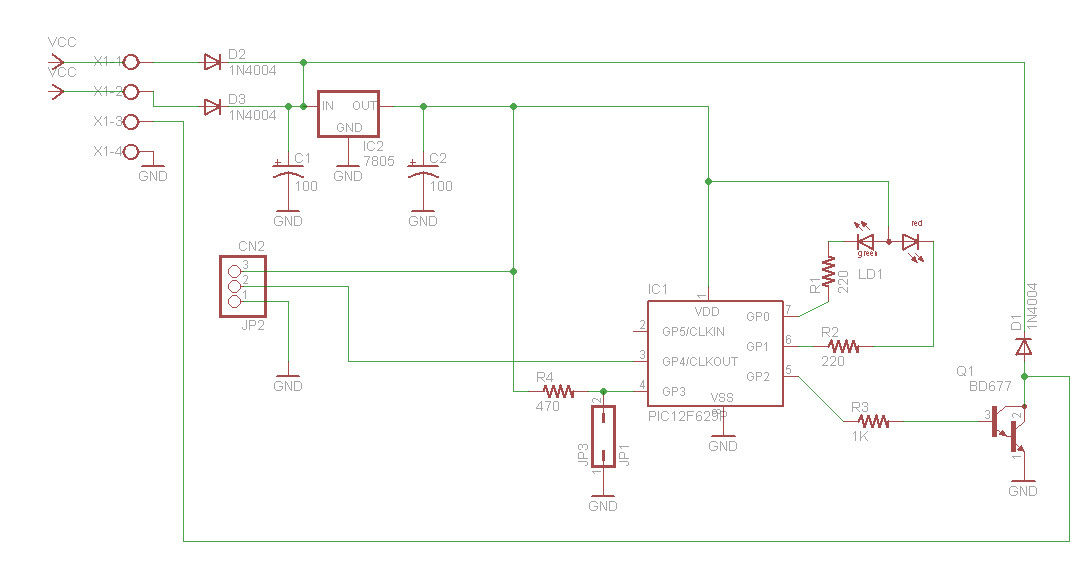
The PCB is fairly straight forward when teamed up with the schematic. There's not much to it...
Print, transfer, etch, drill etc.
The ID12 is wired in standard ASCII mode. The only connections needed are:
|
ID-12 pin |
Signal |
|
1 |
GND |
|
2 |
+5V |
|
7 |
GND |
|
9 |
Data |
|
11 |
+5V |
This means you only need 3 wires going to the ID-12. The others can be jumpered on the chip. If the run is long (more than say 20cm), I would suggest the use of shielded cable as cars are electrically noisy and it might cause dodgey readings.
Once you have the PCB done, solder it all up and program the chip with your fav. programmer. HEX file attached.
For debugging, you can connect pin 2 (GPIO5) and a ground pin to the serial port of a PC's Rx and ground @ 9600 baud to see the actual tag values and what the chip is doing. However, it may not work properly on all PC's without the addition of a max232 chip as it is only pseudo RS232 and not true levels. Not that i have come across any in recent times.
Programming: Power up the immobiliser with the jumper in place. The LED should go green and then go red. You can then program up to 10 tags. The LED will go orange when a tag is read, then go back to red (waiting for another tag). If you want to 'erase' a tag, you must reprogam that position or 'key number'. Best is to just keep reading the same tag over and over till all 10 positions are filled, or reprogramming the pic will clear the eeprom if needed.
Once you have programmed your tags in, you can remove the jumper. The unit is now in 'operation' mode and the LED is red.
When a tag is read, the LED will go orange and If a good tag is read, the LED will go green for 1/2 a second, then extinguish totally and the relay will close. If a bad tag is read, it will go back to red waiting for another tag.
Bench test the setup and once you are happy with it, you can wire it into your car.
The main power for the circuit should come from an 'ignition' circuit on the car. Then connect the 'switched' relay contacts between a feed to the coil(s) or ignition input to your EFI computer.
To operate, turn on the ignition of the car, then swipe the tag over the ID-12, the relay closes, then start the car. If the car is turned off, the process must be repeated.