Paweł Kisielewski
The project is intended for noncommercial usage only
Did you make a mistake while programming fusebits, or purposely disabled reset pin (RSTDISBL) or ISP programming (SPIEN)? No need to buy or make inconvenient HV programmer only for unlock couple of Tiny AVR’s. This Attiny fusebit HV doctor will cure your tiny microcontrollers, by restoring all fusebits to factory settings – nice and easy. Supports all of the serial high voltage interface AVRs, that is:
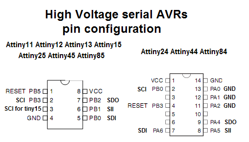
- 8-pins: Attiny11, Attiny12, Attiny13, Attiny15, Attiny25, Attiny45, Attiny85, Attiny22, AT90s2323, AT90s2343;
- 14-pins: Attiny24, Attiny44, Attiny84;
- 20-pins (with special adapter): Attiny261, Attiny461, Attiny861.
For a device to restore the configuration of the fuse-bits of the MCU Atmega family, go to the project: Atmega Fusebit Doctor (HVPP).
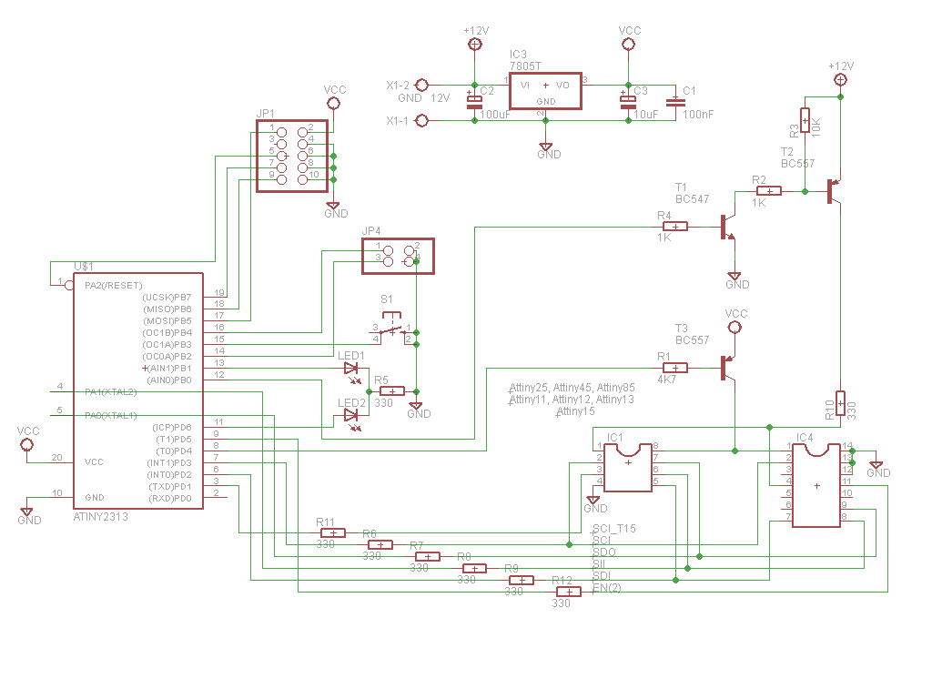
This is very simple and cheap to make, the brain of device is an Attiny2313 uC, couple of resistors and transistors (BC547, BC557), and a 5 V stabilizer. You need 12 V stabilized supply for this. Repair begins after the button START is pressed. Button is active again after 250 ms, so pressing it will reset device and start a new repair process.
LEDs explanation:
- green on – patient successfully cured, fusebits repaired. If lockbits are enabled, just verify fusebits with factory ones – and if they ok – light up green.
- red on – signature problem, can’t read, no device in socket, or no such signature in database.
- green flashing – signature ok, fusebits are wrong. Lockbits enabled, chip erase permission required (read below).
- red flashing – signature ok, no lockbits, but for some reason can’t write new fusebits, can’t pass verification after 10 attempts.
Device uses the High-Voltage Serial Programming (HVSP) to repair fusebits. First of all patient is switched to HV memory programming, then we read signature and check if it’s supported. Then the chip erase is performed if user allows it. Next the lockbits are read, if they not set, patient receives new fusebits, proper for readed model. After that, fusebits are verified, and if they pass the test – this is end of work. If not, doctor will repeat write-verify cycle 10 times, and give up when no success.
Schematic diagram
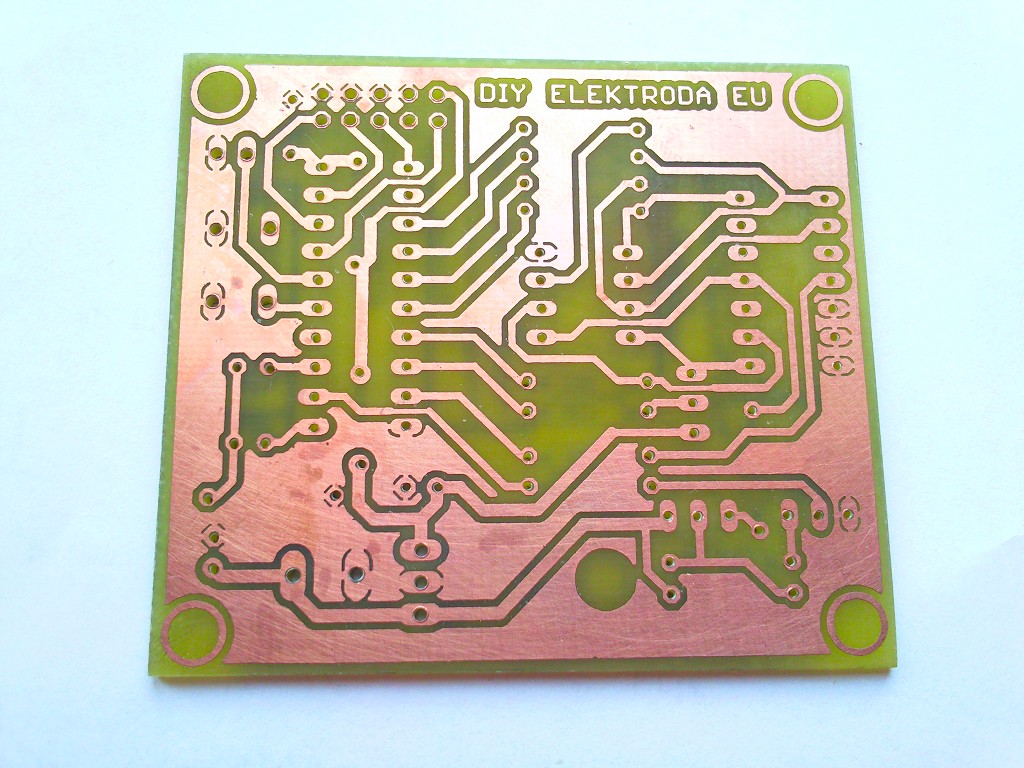
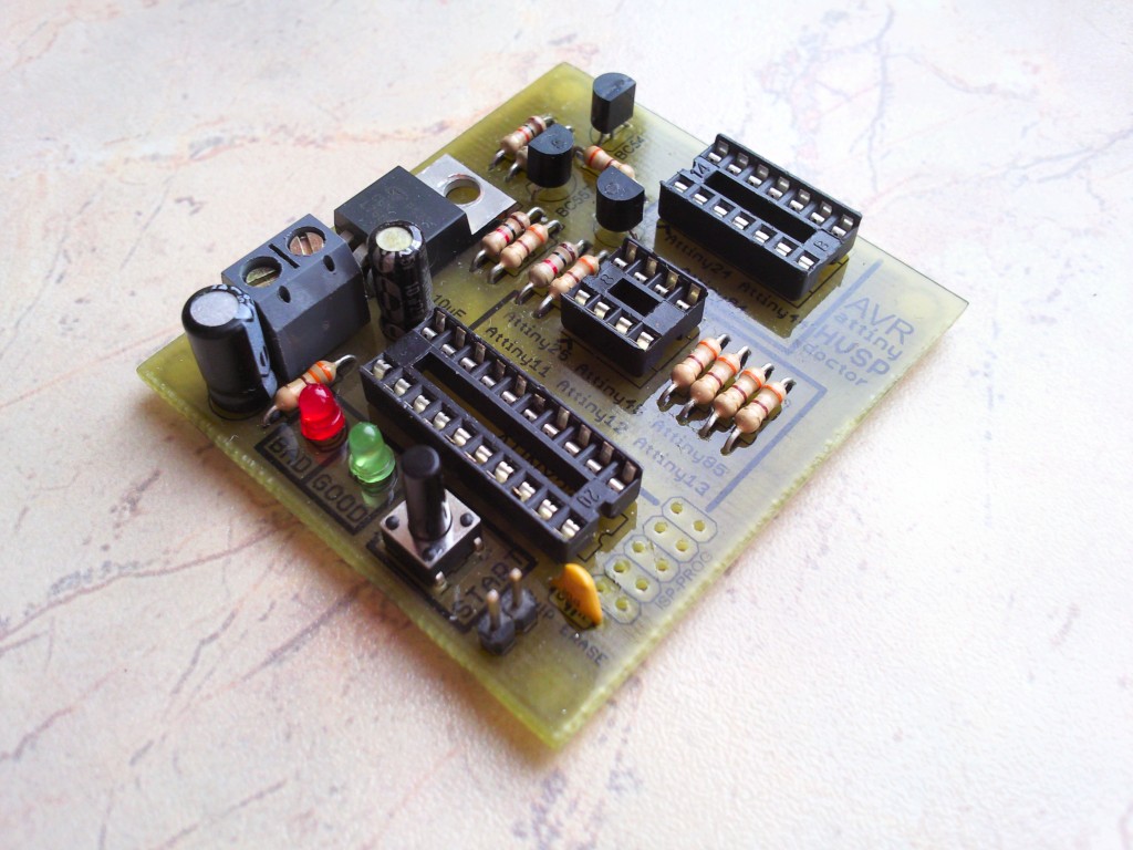
Printed Circuit Board (PCB)
High Voltage Serial AVRs Pin Configuration
You can find two jumpers on board:
- chip erase – permit to erase whole flash memory. If lockbits are enabled, there is no possibility to set new fusebits. And there is only one way to disable lockbits – by erasing whole flash. Jumper close – permission to erase flash
- unknown signature – it happens very rare, but it happens, that uC has erased signature. Signature, calibration bytes, and other data are not permanently stored in uC structure and they can be accidentally erased due to power supply spikes during programming or power cycling. Generally signature will be read as FF FF FF, but chip will work good, flash can be readed and written. If signature will not match to one from doctor database (FF FF FF or 00 00 00 too), closing this jumper will write a universal fusebits pack which will mess oscillator options and such, but will repair functionality of reset (disable RSTDISBL) and ISP programming (enable SPIEN). Microcontroller will be possible to further repair on SPI normal programmer. Do not use this option with Attiny11 or Attiny15.
Fusebits: internal 4 MHz clock not divided by 8. Will be good to select the “fast rising power” too.
Update 3 May 2010: If you are searching for atmega family AVR’s fusebits fix device, then check my next project, the Atmega fusebit doctor.
ATTENTION: FIRMWARE IN BETA VERSION. I was not able to test all of the mentioned uC’s, so if something is going bad, please contact me and i immediately make corrections in code.
DOWNLOAD – eagle 5.4.0 project files, PDF & PNG schematic and PCB’s, HEX & BIN firmware.
UPDATE 9 May 2010: Added support for chips:
8pin: Attiny22, AT90s2323, AT90s2343
Fixed(?) bug with tiny15 and tiny11. Added source code.
I did not test these uC’s – i don’t have it. Program still in BETA version – someone must confirm if it works good.
DOWNLOAD – Firmware V2 HEX and BIN, also source code BAS.
diy.elektroda.eu