This article describes a portable breadboard-friendly adjustable power supply, designed as an ideal supply for Arduino projects and other low-power circuits.
It is capable of providing from 0 V to 5.5 V at up to 0.5 A, and is powered by two rechargable Li-ion cells. The output can be adjusted using a rotary encoder, and the voltage is displayed on a three-digit 7-segment display. The whole circuit is controlled by an ATmega328.
 |
|
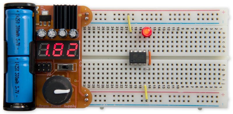
| Figure 1. | Proto Power Supply, fits in a standard breadboard and supplies 0 to 5.5V at up to 0.5A. |
For example, here it's powering an ATtiny85V at its lowest specified voltage, about 1.8 V, running the Blink program: Figure 1.
Specification
Existing breadboard power supplies usually offer 3.3 V and 5 V from a USB input, or an adjustable output from a fixed DC input. However, they all lack a few features that I wanted in a power supply:
- It should be powered from rechargeable batteries, so I wasn't tied to a power socket.
- It should be adjustable down to zero, so I could investigate the behaviour of a circuit with a failing battery, find the voltage at which an LED lights up, check brown-out detection, or build low-voltage circuits.
- It should display the output voltage, so I don't have to tie up a multimeter checking the voltage
As the supply is designed for testing AVR projects I didn't need more than 5.5 V. This means that the supply could conveniently be powered by two 3.7 V Li-ion batteries.
The power supply could have been based on a standard adjustable regulator, such as the LM317, but this would only have allowed the voltage to be adjusted down to about 1.25 V. I therefore chose the LT3080 by Linear Technology, a very nice device which provides up to 1.1 A all the way down to zero volts.
The circuit
Here's the full circuit of the Proto Power Supply:
 |
|
| Figure 2. | Circuit of the Proto Power Supply, based on an ATmega328. |
The LT3080 requires a minimum load for the regulation to work properly, specified on the datasheet as about 500 µA. The simplest way to provide this is to connect a resistor across the output; I chose 220 Ω, which still gives a small reading of 0.05 V with no
load, and draws an additional 25 mA at full voltage. The ripple on the output is below about 2 mV RMS.
Processor
In an earlier article Portable Lab Power Supply I based the project on the ATtiny861, which had just enough I/O lines. However, for this Proto Power Supply I decided to use the more popular ATmega328 because it's more widely available, often at a lower price than the ATtiny861, and although it has more pins, the SMD version actually has a smaller footprint than the SOIC ATtiny861.
In this application there's no need for accurate timing, so we can dispense with an external crystal, and use the ATmega328's internal clock.
Regulators
The LT3080 is available in a variety of different packages. I chose the SOT-223 SMD package. The tab of the regulator is soldered to a large area of copper on the PCB, and I fitted a small heatsink to it with thermal adhesive tape for extra cooling. I've tested the power supply giving a continuous 0.5 A and it stays cool. In theory it should be capable of giving up to 1 A, but at larger currents you would probably need a more substantial heatsink.
To generate the 5.5 V to drive the digital circuitry and provide the reference for the ADC I used an LM317L adjustable regulator, in an SOT-89 package, which can be programmed with two resistors. The voltage is given by the following equation
Values of R1 = 200 Ω and R2 = 680 Ω give us exactly 5.5 V as required.
Rotary encoder
For the rotary encoder I used Adafruit's rotary encoder, which gives 24 pulses per rotation; for other options see Bounce-Free Rotary Encoder.
Display
The circuit uses a low-cost 0.28" 3-digit 7-segment common anode LED display, type 2381BS, available on eBay. You could also use a common-cathode display by changing the Display() routine.
Batteries
The PCB is designed for an AA battery holder. For the power input I chose two rechargable 3.7 V 14250 batteries; these are half the height of an AA battery, so two will fit in the battery holder, giving a total of 7.4 V. Note that most 14250 rechargable batteries are not protected, so they shouldn't be allowed to discharge below 3 V. Alternatively you could use non-rechargeable 14250 batteries (eg Saft), or a rechargeable NiCad PP3 battery.
Construction
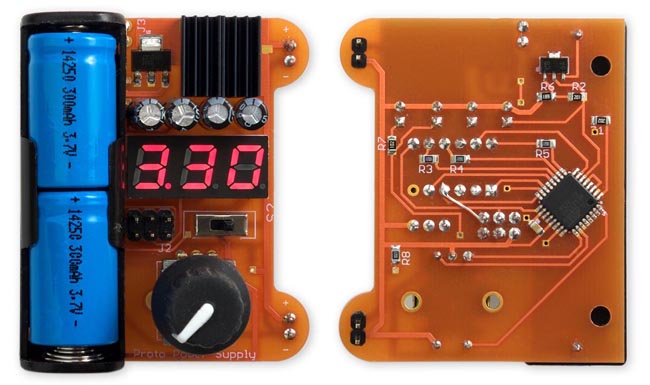
I designed the board in Eagle and sent it to Ragworm in the UK for fabrication. The circuit uses a mixture of SMD and through-hole components, to achieve a compact layout while using readily available components: Figure 3.
 |
|
| Figure 3. | The front and back of the completed Proto Power Supply circuit board. |
None of the SMD components are particularly small so it should be possible to solder them by hand, using a fine-tipped soldering iron, but I used a Youyue 858D+ hot air gun set to 250 °C. Fit the SMD components first, and then do the through-hole components.
The program
This section explains the various sections of the Proto Power Supply program. See the program listing available in the Downloads section.
Reading the rotary encoder
The rotary encoder is connected to two inputs, PC2 and PC3. They are configured with input pullups in setup(), and PC2 is configured with a pin-change interrupt.
The pin-change interrupt service routine then reads the state of the two inputs, determines which direction the change in value should be, and calls ChangeValue(). Variables a and b hold the current states of the two inputs, the global variable a0 holds the previous state of a, and c0 holds the cleaned-up signal.
This is based on my earlier article Bounce-Free Rotary Encoder. [1]
Generating an analogue output
The power supply voltage is controlled by an analogue output, generated by a PWM signal on PD3. This is generated using Timer/Counter2, which is configured in setup() to generate phase-correct PWM.
Rotating the rotary encoder calls ChangeValue() which increments or decrements the value of the global variable Count.
This in turn calls SetVoltage() which changes the Timer/Counter2 compare match value OCR2B.
Reading the output voltage
The regulated output voltage is read by the analogue input ADC0, on PC0. This is configured in setup() to use VCC as the reference voltage. The analogue value is read by the routine ReadADC().
Displaying the voltage
Finally, the analogue voltage is displayed on the three-digit 7-segment display. For simplicity I used the same timer, Timer/Counter2, to multiplex the display. Every 220 counts the counter overflows, and this is used to call an interrupt service routine ISR (TIMER2_OVF_vect).
This in turn calls DisplayNextDigit(). This puts the appropriate segment data onto PORTB for the next digit to be displayed, and then takes the digit common line high on PORTD. The number to be displayed on each display digit is specified by the array Buffer[].
Every fourth cycle this routine reads the ADC, and calls Display() to write the appropriate values to the display buffer, Buffer[]. To prevent the display flickering between two adjacent values it only updates the display if the voltage has changed by at least 10 mV.
Overload trip
The LT3080 incorporates short-circuit protection, limiting the output current to about 1.4 A, but this is still enough to damage an incorrectly-wired circuit. I therefore incorporated an overload trip, which is triggered if the target voltage, set by the rotary encoder, is more than 500 mV higher than the measured output voltage. This is handled by a check in DisplayNextDigit(), which sets the Overload flag if an overload has occurred. The voltage is set to zero and the display shows dashes. To reset the overload trip rotate the encoder.
Push-button preset
The rotary encoder button presets the voltage to 3.3 V. The button is wired to PD2 which is configured in setup() to generate an interrupt on INT0.
The interrupt service routine then just simply sets Count to 3.3/0.025 or 132.
Compiling the program
You can program the ATmega328 using ISP (in-system programming) via the 6-pin ISP connector provided on the PCB. I used a USBASP programmer, available cheaply on eBay(or on Aliexpress), which includes a ribbon cable that connects to the ISP connector on the Proto Power Supply board. Alternatively you could use a Sparkfun Tiny AVR Programmer, or an Arduino Uno as an ISP programmer.
The Arduino IDE doesn't include a configuration using the internal clock, so I created one which you can download from GitHub: ATmegaBreadboard. [2] After copying it to the hardware folder in your Arduino folder, select the ATmega328 option under the ATmegaBreadboard heading on the Boards menu. Then choose B.O.D. Enabled (4.3V), ATmega328P, and 8 MHz (internal) from the subsequent menus. Choose Burn Bootloader to set the fuses appropriately; then select Upload to upload the program.
Alternatively, get it on GitHub here together with the latest Eagle files for the PCB: Proto Power Supply on GitHub. [3]
