This article shows how to build a small, cheap and simple frequency meter, without any fancy, out of reach components. The simple proposed design can measure frequencies up to 40 Mhz with errors below 1%! This degree of precision will be more than enough to debug most of your analog and digital circuits, and will give you the ability to analyze many aspects that you were unable to see before.
The frequency meter is build on a veroboard, using only 3 components and 8 resistors. It is designed to be plugged into any standard bread-board.
1.The hardware
Figure 1 Schematic diagram.
As you can see in figure 1, the design is built on a ATMEGA16 microcontroller from Atmel. There are no crystal oscillators, as we are using the internal RC oscillator, calibrated to 8 MHz.
The frequency measurement probe is connected to W1 terminal, which is then fed to the pin PB0 and the clock input of the 74HC191 4-bit counter. The 4-bit counter will be used to divide the measured frequency by 16 before feeding it to the microcontroller. As you can see, all the features of the counter aren't used, only the Q3 output is used, whose frequency will always be equal to the input frequency divided by 16.
The 7 segments display used is composed of 4 cells all integrated into one package. This reduces the number of wires to enable the different cells.
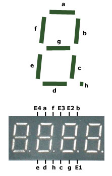
Figure 2
The display we used is common anode type, and had its leads arranged according to the diagram in figure 2, and most of the 7 segment cells of this type will follow those standard connections. However, if you use different type of 7 segment display, the software can be very easily adapted to accommodate the changes. The pins E1 to E4 lets you enable one of the 4 cells, E1 enables the right most one.
Since we are using an ATMEGA16 microcontroller that can source up to 40mA of current per I/O pin, we don't need transistors, so the 4 enable signals of the 7 segment display is directly connected to the microcontroller.
The wire connection W2 is to connect to ground, to allow measurement of frequencies on devices that do not share the same power supply as the frequency meter itself. (Remark, for one circuit to be able to measure an signal on another circuit, they must share the same ground voltage, se we connect them together.)
Finally, J1 is a connection for the ISP programmer (In System Programmer). In need, after you finish the project you will spend 10 minutes doing nothing by calibrating your frequency meter, and adjusting some variables to make the display clearer or to reduce the flickering of the numbers being displayed. That's why we added this ISP connector, because we will need to update the code of the microcontroller often.
2. Frequency measurement algorithm
We all know - at least most of the visitors that made it to that website! - that "Frequency is a measure of the number of occurrences of a repeating event per unit time". but measuring frequencies with digital tools such as this microcontroller that have its limitations involve some further studies to achieve the required results.
The maximum frequency that can be sampled by one of the counters of the ATMEGA16 cannot exceed the CPU clock divided by 2.5. Let's call this frequency Fmax. So, assuming the ATMEGA16's CPU is clocked at 8 MHz, we can directly measure frequencies up to 3.2 Mhz. Frequencies above that limit will be measured as 3.2 MHz or less, since not all the pulses will be sampled. To be able to measure frequencies above F_max, we use a 4 bit counter as a frequency divider, dividing the measured frequency by 16. This way we can also measure frequencies up to 16 times Fmax, but due to the limitation of the 74HC191 counter, the actual maximum measurable frequency wont exceed 40 MHz.
The algorithm that we developed measures both the original frequency (let's call it F_o) and divided frequency (F_d). in normal conditions, when the frequency is below F_max, the following relation is true:
Fo=16×Fd;
But as F_o approaches to F_max, more and more pulses wont be sampled, and the the relation above will obviously become:
Fo<16×Fd;
And hence the limit of the microcontroller can be automatically detected.
The frequency meter starts by selecting the original frequency for processing and display, and as soon as it detects that it reaches F_max (using the method described above), the divided frequency is selected instead.
This algorithm can be summarized in the following flow chart (figure 3)
Figure 3
The software
The source code is detailed with as much comments as I could, but you may need some more explanations to understand the code:
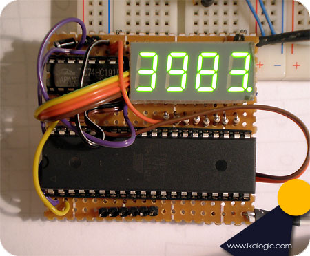
- The code is made such that the number being displayed is in KHz. For example, if you see on the 7 segments the number "325.8" that means 325.8 KHz, "3983" would mean 3983 KHz (or 3.983 MHz). If the number is in tenth of megahertz, it is displayed with an "m" at the end like "22.3m" meaning 22.3 MHz.
- Timer/Counter 0 is used to count incoming pulses directly
- Timer/Counter 1 is used to count incoming pulses divided by 16
- Timer/Counter 2 is configured as timer with a 1024 prescaller (counting CPU frequency divided by 1024). It is used to call the "frequency calculation and selection algorithm" every timer period T. T is defined as "Т=1024×256/Fcpu".
- The constant "factor" defined in the top of the program as "31.78581" have to be calibrated by measuring a known frequency. This factor was initially calculated as the following:
factor=Fcpu/(1024×256)=8.E6/(1024×256)=30.51757
But due to the fact that there is some delay between the time the Timer_2 overflows and the time where the counted frequency is actually processed, this factor need some calibration to reflect more accurately the reality of the frequency being measured.
The Anti-flickering algorithm is complicated but very effective, specially in measuring frequencies that are unstable. It will totally prevent the display from quickly switching between various values, while still showing accurate values, and quickly change if the frequency being measured "really" changes.
One last note, the ATMEGA16 is chipped with a 1 MHz internal oscillator enabled. To set the internal oscillator to 8Mhz, you have to use some programmer (like our ISP programmer) to change the fuse bits of the micro controller to adjust the internal oscillator's frequency. (For 8MHz, the CKSEL3..0 fuses have to be set to '0100').
The zip file for the project containing the C code and complied HEX file - download.