Introduction
A ±500 V protection circuit for low voltage high impedance measuring instruments is shown in Figure 1. The protection is accomplished by limiting the amount of current going into the measuring instrument. The circuit will protect against destructive high voltages inadvertently connected to the probes (VMEAS) of up to 500 VDC of positive and negative polarity.
 |
|
| Figure 1. |
Circuit Description
The circuit consists of two transistors, Q1 and Q2, and one resistor, R1. Both Q1 and Q2 are LND150N8, 500 V N-channel depletion mode MOSFETs with gate-to-source ESD protection in a SOT-89 surface mount package. Q1 and Q2 are configured back-to-back as two constant current sources with a nominal value of 1.0 mA. Resistor R1 sets the current limiting value. Figure 2 is a typical low voltage high impedance measurement instrument. Figure 3 is a simplified equivalent circuit showing the protection scheme.
Under normal operation, the absolute value of VMEAS is less than the supply voltage of the circuit. Q1 and Q2 will be fully on with a maximum guaranteed RDS of 1.0 kΩ. Since the instrument’s input impedance is typically very high, say above 10 MΩ, the additional 2.0 kΩ series resistance from Q1 and Q2 will not affect measurement accuracy.
 |
|
| Figure 2. |
Under the fault condition, the absolute value of VMEAS is greater than the supply voltage, Q1 limits the current to 1.0 mA against large positive voltages and Q2 limits the current to –1.0 mA against large negative voltages across VMEAS.
 |
|
| Figure 3. |
For example, if VMEAS is connected to ±500 V, Q1 and Q2 will limit the input current to ±1.0 mA causing the input voltage to the measurement instrument to clamp to 1.3 V above its supply voltage (when R = 600 Ω) and 0.7 V below ground.
Typically the measuring instrument has ESD protection diodes connected from both probes to its power supply and ground. The ESD protection diodes can usually handle 1.0 mA continuously. In case there are no ESD diodes provided, external diodes D1, D2, D3, and D4 can be added.
Calculation for Resistor Value
For a current limiting value of ±1.0 mA, R1 can be approximated by the following equation:
where,
ID = desired constant current value,
VGS(OFF) = pinch-off voltage, and
IDSS = saturation current at VGS = 0 V.
VGS(OFF) and IDSS are device characteristics and will vary from lot to lot. Actual constant current values are not critical as long as the power dissipation of the LND150N8 is less than 600 mW.
 |
|
 |
|
| Figure 4. |
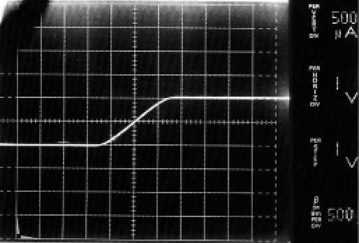
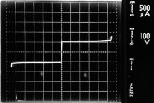
Figures 4a and 4b are pictures of current due to VMEAS vs. VMEAS voltage of the actual circuit. R1 was chosen to be 1.0 kΩ.
Conclusion
The high voltage protection circuit is ideal for both bench measurement and handheld measurement instruments. It is simple, reliable and cost effective. It eliminates the possibility of input damage to very sensitive and expensive high impedance devices within the measurement instrument.
