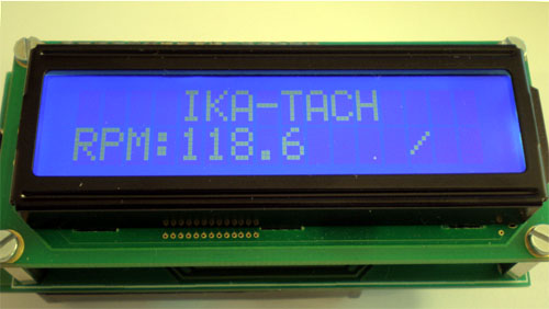
This new contactless tachometer - is the device based on an ATMEGA48 AVR micro controller from Atmel, and is able to measure very high RPMs, as well as very low ones. It is based on an IR (Infra Red) opto-couple to detect shaft rotation.
Principle of operation
A tachometer is a device used to measure the number of revolutions per minute of a rotating shaft (see wikipedia's definition). It is mainly used to measure the speed of motors in planes, cars, motor bikes or even bicycles.
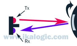
The heart of this tachometer is an IR sensor, also called opto couple, which is a diode and photo diode in one package. This opto-couple will send IR beam on the shaft to detect it's rotation. For that purpose, a small reflective sticker is added on the shaft, so that each rotation of the shaft will cause a "pulse" of IR light to be reflected. Figure below shows a beam or IR light being sent to a rotating shaft having a reflective sticker on it.
The sensor that was used is the TCND-5000 from Vishay Semiconductor.
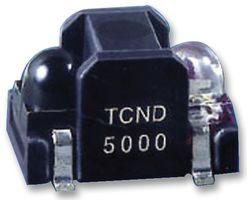
After testing various equivalent products, we decided to you this one for some factors, the most relevant being :
- The packaging takes care of the optical isolation between the sender and the receiver.
- The Emitter LED can sustain relatively high currents, and thus, can allow detection of rotating shafts ant bigger ranges.
So, to recap, using that opto couple we can count the time taken by the shaft to execute a complete revolution. Then, when you have that time information (let's call it T and let's assume T's using is seconds), the RPM is simply calculated as [60/T].
Getting useful data from the IR Opto-couple
To reduce cost and hardware complexity, and to increase system flexibility, we decided to connect the IR sensor directly to the ATMEGA micro controller, and let it do all the signal processing. This was difficult because the signals coming from the photo-diode are very noisy, and are constantly biased by the ambient light. So the challenge was to build a system that would automatically adapt to ambient light and also adapt to the distance from the shaft being measured.
Figure below shows an example of the analog signals we could read from the senor. All the noise around each high/low transition is
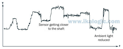
Beside the fact that the signal is noisy, at each transition between ON and OFF (ON being when the shaft rotates and the sensor "sees" the reflective sticker), a huge amount of oscillation occur causing the controller to be totally confused!
We wanted to use the comparator that is integrated in the ATMEGA48, but due to all those factors, it was not possible, we needed to process the analog signals before even trying to count the cycles.
The solution we found was to constantly estimate the average intensity, based on the maximum and minimum intensities retrieved from the sensor, then "create" a hysteresis around that average intensity.
This hysteresis will be used to prevent multiple cycles counts during noisy High/Low transitions.
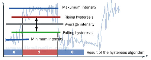
Here is how it works in more details: when the noisy signal is raising from a low state (no IR reflection) to a high state (IR re flexion), the algorithm will only consider the signal to be high if it crosses the "rising hysteresis" level shown on the graph, and will only consider the signal to be low if crosses the "falling hysteresis" level. This will prevent most possibilities of having errors caused by the noisy signal.
The hardware
The hardware is fairly simple and compact, thanks to the small IR sensor and the battery pack at the back.
The schematic below how simple it is. Notice that there is no potentiometer for the contrast adjustment. this would take too much place and it is not reliable to always have to adjust it, so instead we designed our own contrast regulation system based on a PWM generator and a low pass filter (R3, R4 and C2).
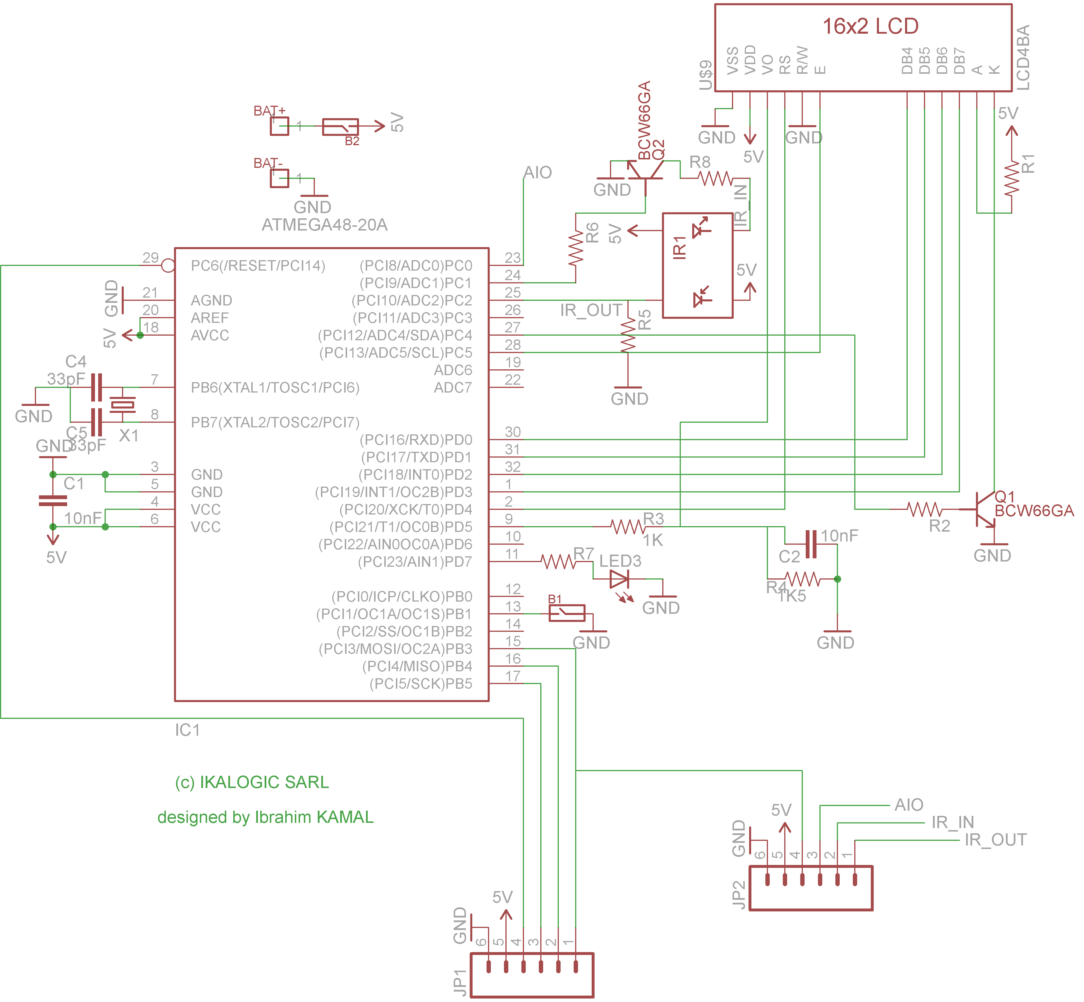
Notice that there is an additional interface (JP2) to allow the user to hook any additional sensor. JP1 is used for ISP programming of the micro controller. JP1 can also be used to transfer RPM data out of the device.
| Component | Value / comment |
| IC1 | ATmega48 microcontroller |
| Q1, Q2 | BCW66G Transistors |
| C1, C2 | 10 nF |
| C4, C5 | 33 pF |
| X1 | 20 MHz QUARTZ |
| R1, R2, R7 | 470 Ohm |
| R3 | 1 Ohm |
| R4 | 1.5 Ohm |
| R5 | 1 MOhm |
| R6 | 110 Ohm |
| R8 | 70 Ohm |
| LED3 | CMS LED |
| IR1 | TCND-5000 Infra-Red Opto-couple |
| B1 | Side push button |
| B2 | ON/OFF switch |
| JP1 | ISP programming port |
| JP2 | Extension port |
As you can see in the short video below, the sensor is located at the back, next to a red narrow-beam LED that glows to help you point the invisible IR sensor beam to the target shaft.
Demonstration video