Part 1. Schematic
Part 2. Software
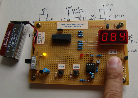
Output
The use of this device is very simple. Turn the power on, and you will see all zeros on display for few seconds. Wait till the display goes off. Now place your forefinger tip on the sensor assembly, and press the start button. Just relaxed and don’t move your finger. You will see the LED blinking with heart beats, and after 15 sec, the result will be displayed.
Important note:
I am adding these paragraphs to provide further detail on the sensor and signal conditioning part of this project.
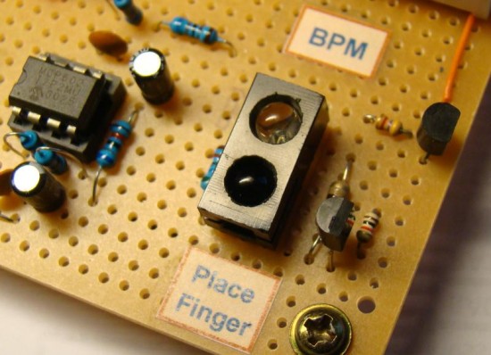
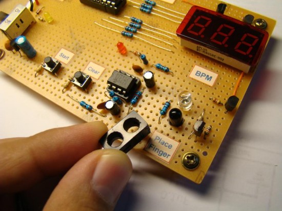
The harder part in this project is the signal conditioning circuit that uses active low pass filters using OpAmps to boost the weak reflected light signal detected by the photo diode. The IR transmitting diode and the photo diode are placed closely but any direct crosstalk between the two are avoided. Look at the following pictures to see how I have blocked the direct infrared light from falling into the adjacent photo diode. Besides, surrounding the sensor with an opaque material makes the sensor system more robust to changing ambient light condition. I have used separate IR diode and photo diode, but you can buy reflective optical sensor systems that have both the diodes assembled together.
The 150 Ω resistance in series with the IR diode is to limit the current and hence the intensity of the transmitted infrared light. The intensity of IR light should not be too high otherwise the reflected light will be sufficient enough to saturate the photo detecting diode all the time and no signal will exist. The value of this current limiting resistor could be different for different IR diodes, depending upon their specifications.
Here’s my practical test circuit that I used to find the appropriate value of the series resistor for the IR diode I used.
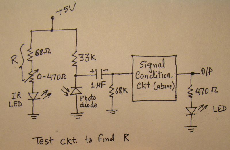
First I used a 68 Ω resistor with a 470 Ω potentiometer in series with the IR diode. Placing a fingertip over the sensor assembly, I slowly varied the potentiometer till I found the output LED blinking with heartbeat. Then I measured the equivalent resistance R and replaced the 68 Ω and the potentiometer with a single resistor closest to R. But you can also keep the potentiometer in your circuit so that you can always adjust it when needed. You should keep your fingertip very still over the sensor while testing. Once you see the pulses at the output of the signal conditioning circuit, you can feed them to a microcontroller to count and display.
