Ronak Desai, Cypress Semiconductors
This article explores design techniques and challenges for implementing an electronic bike (E-Bike) built using a microcontroller or Programmable System on Chip (PSoC). Current E-Bike systems use a microcontroller with external signal conditioning and comparator circuitry to drive the three-phase motor; external ADC and external amplifiers for different sensor inputs; relay driver circuitry for brake light, headlight, and directional lights; LED/ LCD displays; and temperature measurement (Figure 1).
Programmable SOC devices can be used in E-Bike applications as a single-board system for motor control, analog measurement, and direct drive LCD display. Programmable SOCs can also support capacitive sensing technology to replace mechanical buttons on the keypad. In addition, SOC devices use internal PWM, MUX, and comparators for driving and controlling the three-phase motor, internal ADC and PGA for sensor inputs battery monitoring, and temperature sensing using a temperature sensing device like a thermistor or RTD. The device can also directly drive the relays for the brake light, headlight, and directional lights, as well as direct drives the LCD display of temperature, battery status, speed, distance travelled, and any error/warning messages.
Using IDE-based tools, all interface and logic can be designed for the SoC. These tools also have readily available component blocks for designing more complex logic such as monitoring a capacitive sensor for the interface, an ADC for analog sensors and other inputs, driving the PWM for a buzzer, DAC, and a segment, character, or graphical LCD display. Thus, with a programmable SOC, the development and product cost of an E-Bike system can be substantially reduced.
 |
|
| Figure 1. | Block diagram of a basic E-Bike system. |
Microcontroller:
The microcontroller is typically used for different sensor input detection (i.e., throttle inputs, temperature sensor, battery input, fuel sensor, obstacle sensors), A/D conversion, output comparison components, and driving and controlling the three-phase brushless automotive motor. An ultra-low power microcontroller is required as an E-Bike is a battery-operated system. The microcontroller is also part of the central locking system, and can be used to communicate with different external devices used in the vehicle. Using a microcontroller whenever a brake is pulled automatically stops the motor spinning and prevents the motor from wearing down the brake pads faster than a standard human-powered bike.
Hub motor/Wheel motor:
Typically, a brushless motor is used, either sensored (Hall Effect) or sensorless, for reliable and efficient operation.
Rechargeable Lead Acid/ Lithium Battery:
A variety of battery types are used in E-Bike applications, from lead-acid to lithium batteries. The rechargeable lead-acid battery is commonly used in automotive applications.
Display and Keypad:
Typically, the LCD display with backlight is used for showing the temperature, battery input, speed, distance traveled, and any error/warning messages. It can also show levels of pedaling assistance and energy generation. A mechanical button-based keypad is used in automotive applications. A keypad also enables anti-theft capabilities to protect the bike.
Power management:
This subsystem provides power to run functional blocks and oversees battery activity. The host microcontroller with comparators and discrete logic can be used to manage a lead-acid battery. This approach also provides safety and critical information about battery to the microcontroller and user.
Theory
Currently, 16-bit and 32-bit microcontrollers are used for E-bike systems. The microcontroller controls and manages all the functions and features of the vehicle. Once the user turns the ignition key to start the vehicle, an input goes to the microcontroller so it can start the three-phase brushless automotive motor. The microcontroller receives the various vehicle input signals from the user and moves the vehicle appropriately. The microcontroller drive the three-phase brushless automotive motor as per the speed selected by the user. The speed of the motor will vary and can be controlled as per acceleration and brake sensor input from the user.
The microcontroller uses either internal or external serial EEPROM (I2C/SPI based) for storing data like distance readings. The microcontroller also uses a real-time clock (RTC) to display accurate time on the display.
Temperature measurements are made using and on-board RTD or thermistor-based temperature sensing device. The E-Bike system can also use an obstacle sensor to get information about nearby vehicles while parking. A fuel sensor gets information about fuel in the engine, and the microcontroller can monitor the battery input and display it on the LCD display. Relay driver circuitry is used to switch ON/OFF the brake light, headlight, and directional lights.
The power supply section consists of a rechargeable lead acid or lithium battery as a power source. It must also have provisions for the battery charger. The battery input is down converted to a DC voltage to power the microcontroller and other circuitry. The ignition key enables and disables on-board regulators. The power supply section also has protections like battery, over-current, over-heating, and start-up fail condition protection circuitry. OEMs may also want to provide provisions for charging external devices like cell phones.
 |
|
| Figure 2. | PSoC based E-Bike solution Block diagram. |
Implementation of an E-Bike System
To show an actual implementation of an E-Bike system, this article shows a design based on the Cypress PSoC 4. The PSoC 4 device is s a combination of a microcontroller with digital programmable logic, high-performance analog-to-digital conversion, op-amps with Comparator mode, and standard communication and timing peripherals. The microcontroller is a 32-bit ARM Cortex M0, operates at up to 48 MHz, and has up to 32 KB Flash with up to 4 KB SRAM and 2 KB internal EEPROM.
This implementation uses an on-board 6 P-Channel MOSFET and gate driver circuitry to drive a three-phase brushless motor. The PSoC 4 device has an internal PWM, clock, multiplexer, and comparators for driving and controlling the three-phase brushless motor. In addition, an internal 16-bit PWM will be used to drive the FET-based gate driver circuitry controlling the motor. The duty cycle of the PWM varies, based upon the speed required as set by the user.
The PSoC 4 has an internal op-amp, PGA, comparators, and 12-bit 1MSPS SAR ADC with differential and single-ended modes including sample-and-hold (S/H) capability. This ADC is used to control the speed of the motor by varying the PWM duty cycle as well as to measure different sensor inputs for battery monitoring, low-cost temperature sensing, obstacle sensing, and fuel sensing. Thus, the system does not require any external amplifies, ADCs, or comparators.
With two current DACs (IDACs), the system has general-purpose sensing capabilities or the ability to utilize capacitive sensing technology on any pin. The PSoC 4 architecture supports a capacitive sensing component supporting both manual and auto tuning. Having a capacitive-based interface is helpful in waterproofing the overall E-Bike system. It can also directly drive the relay for the horn, brake light, headlight, and directional lights as well as the LCD display. With an operating range of 1.71V to 5.5V, the device can easily interface with external peripherals for other functionality. In addition, PSoC 4 supports two independent run-time reconfigurable Serial Communication Blocks (SCBs) with re-configurable I2C, SPI, or UART functionality useful for internal and external peripheral communication.
This implementation uses a rechargeable lead acid or lithium battery as a power source. The input voltage is down converted by an on-board step-down regulator. The low operating voltage at 1.71 V and ultra low power operation along with hibernate and deep sleep modes allows a wakeup-time versus power trade-off to support larger battery life.
Using the PSoC Creator IDE tool, all the interface and logic can be designed using readily-available component blocks like SARADC and PGA for analog sensors and other inputs; components like PWM, CLK, MUX, and comparators for motor drive applications; components for directly driving character and segment LCD; a CAN Component for CAN protocol interface in automotive applications, and an RTC component for real-time measurement using an internal system clock so the system does not require external clock/oscillator circuitry.
PSoC Creator also enables engineers to access an entire tools ecosystem with integrated compiler tool chains, RTOSes, and production programmers. Developers can Create and share user-defined, custom peripherals using a hierarchical schematic design. They can then automatically place and route selected components and integrate simple glue logic, normally located in discrete multiplexers.
Over-current protection is used to turn off the motor-driving PWMs and thus stop motor operation. The device has comparator-based triggering of PWM Kill signals that can be used to terminate motor-driving when an overcurrent condition is detected. The input to this block is from the bus current. The cut-off reference to this block is set to the maximum current that can be drawn by the motor. The bus current input is given to the comparator and the cut-off reference, which is configurable, is set by the DAC. The comparator output is set high if the bus current is lower than the reference threshold. The comparator output is connected to the “KILL” signal input of the PWM. When this “KILL” input is high, the PWM output is turned off, thus preventing the motor from being damaged. The implementation of this complete block will be by using PSoC creator components and will not require any firmware written by the designer.
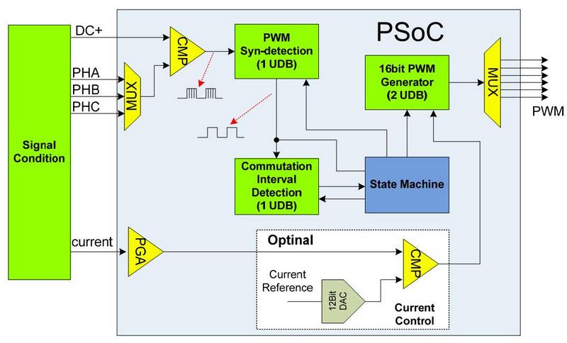
Sensorless motor control
Sensorless motor control does not require Hall sensors but rather uses a back-EMF zero-crossing detection technique to control motor movement. When the motor rotates, each winding generates a voltage known as the back Electromotive Force (Back EMF) that opposes the main voltage supplied to the windings. Back EMF polarity is in the opposite direction of the voltage used for the winding excitation and directly proportional to the motor speed.
 |
|
| Figure 3. | PSoC based Sensorless Motor control. |
Sensorless Motor control In Figure 3, back EMF signals from the three phases terminate and the DC bus is scaled and routed to the PSoC. The PSoC will switch the terminate input to the comparator using the MUX, and then compare it with the DC bus voltage. Cascaded digital logic will filter out the PWM signal to get the real zero-crossing signal. The microcontroller will decide the commutation according to this information.
An optional current control will be applied to the PWM output control to regulate the motor current. This inner loop is based on a comparator: the feedback bus current is compared with the reference current value that is provided by a 12-bit DAC. Changing the DAC output will modify the output current value.
Sensor-based (HALL effect) motor control
Sensor-based brushless motor control uses a Hall sensor input to detect the rotor position and thus control motor movement. It provides Hall sensor inputs to the microcontroller and works as a closed loop system. This is helpful for automatic speed locking for longer drives.
Design Challenges
A high-performance, intelligent microcontroller is required with a higher MIPS CPU core, faster ADC (>= 500Ksps @ 10-bit), internal Flash and SRAM memory, internal EEPROM, analog, and digital peripherals to perform key functions like high performance analog measurement, CAN interface, three phase Motor control, LCD drive, Low power operation, RTC, Interfaces with different external protocols.
The system can have a low-cost front-panel design with different features like buttons and LED/ LCD interfaces. Alternatively, capacitive sensing can be used to implement button, slider and proximity sensors on the front-panel. Meeting capacitive sensing performance requires (i.e., signal-to-noise ratio) with nearby LEDs (PWM-based) on the front panel can be a design challenge for system designer.
Power MOSFET selection with Low Ron and Low gate capacitance is required for driving three-phase motors. Designing the board with high-power MOSFET driver circuitry and handling high on-board current from a battery input is another design challenge for board designers. As this system involves electro-mechanical construction, designing a compact and cost-effective electro-mechanical system can be challenging, as well certifying the final design. Furthermore, the E-Bike system needs to be designed to achieve greater mileage.
Fault detection with a recovery mechanism is required for all automotive applications. A power supply design with battery protection, over-current, overheating, and start-up fail condition protection is required as well.
Developers will also likely want to use a One-Time Programmable (OTP) device to prevent reverse engineering of the firmware by competitors and hackers.
System Limitations
Capacitive sensing technology is supported to replace mechanical buttons with a touch-based keypad. This reduces failure due to mechanical buttons and provides better product reliability. CapSense SmartSense components are also supported, which auto tune the sensitivity of capacitive sensing buttons and sliders to eliminate manual tuning by developers. Capacitive sensing also improves waterproofing of the final system.
Implementation of a touchscreen-based design on the front panel instead of an LCD display and keypad will provide a better user interface and flexibility for users. An interface for external devices like iPod/iPhone can be added so the system can communicate to media players across a UART or USB interface to play music, control playlists, and charge devices.
Failure Analysis and Returned Materials: Increasing the number of internal and external interfaces on the board is going to increase the number of ways that an intruder can create havoc on the system. This is one of the single largest limitations of this embedded system.
E-Bike systems used in automotive applications are currently implemented using microcontrollers. PSoC is a combination of a microcontroller and ASIC. Using PSoC Based E-Bike solution one can reduce the complete product cost (by reducing the BOM cost) and project cost in the automotive industry.