Part 1. Schematic and basic components
Operation of the circuit:
For setting RTC date/time (or for debugging mode):
- Connect the microSD module, insert the microSD card
- Connect the RS232 cable with the circuit. Set-up hyper terminal with 19200 baud, no parity, 8-bit data, 1 stop-bit and flow-control as 'None'
- Connect the power cable and power on the circuit while keeping the push-button pressed
- Green LED will glow in the circuit board
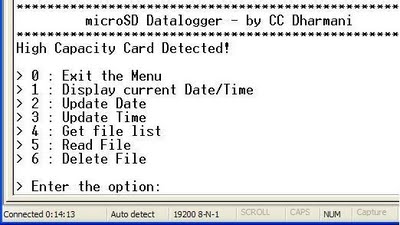
- A menu will be displayed on the Hyper terminal as shown in the figure below. Select desired option and follow the displayed instructions
- When date/time is set or debugging done, select option '0' to come out of the menu and start functioning a s data-logger
- At this point, the RS232 cable can be removed
Operation as Data-Logger:
- Connect the power cable and power on the circuit
- Green LED will glow
- Whenever the data-logging is required, press the push-button
- Red LED will glow, indicating that the recording has started
- To stop recording, press the push-button again, recording will stop and red LED will turn off
- Files stored in the card can be read using a PC card-reader or using hyper-terminal with the circuit started in debugging mode
The operation is very simple as it uses just one push-button and an LED indication. In case of any error in accessing the card, red LED will blink continuously. In such a case, you can start circuit in debug mode (with terminal) and see the error messages.
Files are stored with the date as a name and .CSV extension. For example, data-logging done on 10 May 2011 would be stored in "10052011.CSV" file. Since the date is the name of file, everyday a single file is created and all the data recording done in a day goes into single file, no matter how many times the recording is stopped/started. First column of the file shows date, second shows time and next 8 columns show data from the 8 channels.

A file created during testing is shown in the figure below, where 5 sec interval was set for measurements (click on the image to enlarge it). Here channel-0 was used for LM35 temperature sensor, and remaining channels measure voltage. 5v was connected to channel-1 and 3v Li cell was connected to channel-3 (Channel 2 & 4 show some small voltages due to noise from voltages connected to nearby channels, which can be corrected by using bypass caps).
The interval between two measurement cycles is defined in main.c file, which can be set as per the user requirement. Basically, the program forms a dataString in every measurement cycle and appends this string to the file, if the file already exists or it creates a new file (for example, during the first recording in a day). You may go through the comments in the source code file for more info.
Note: Make sure that RTC circuit is properly connected, otherwise the code will simply hang waiting for receiving date & time from RTC
Download project files
The source code is written in AVR-GCC format using winAVR with AVRStudio-4 - download
