The idea
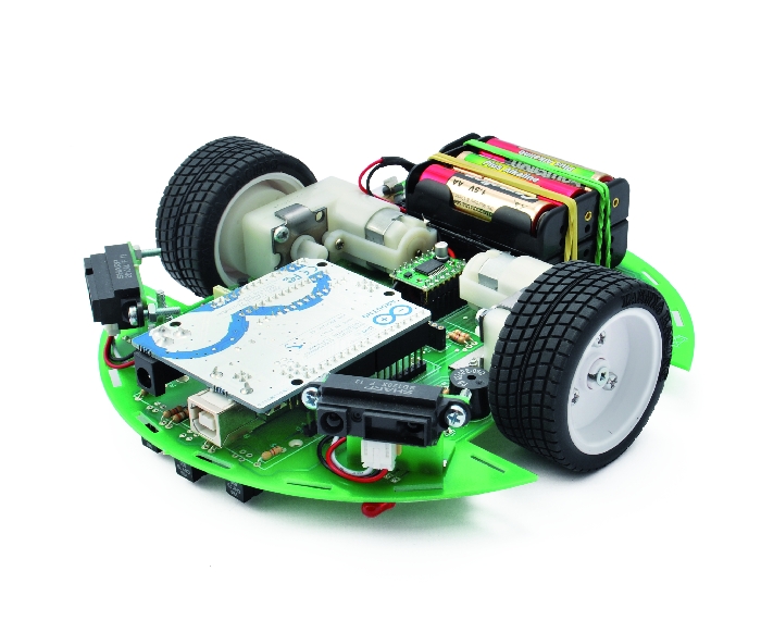
Ardusumo is a universal platform to build robots on wheels that can move around avoiding obstacles using infrared sensors and follow routes marked with dark lines on a white background (Figure 1).
We have created Ardusumo to bring young students to the world of robotics: if suitably programmed, Ardusumo allows robots to perform various autonomous movements, it integrates sensors and actuators of various types with wheels and electric motors.
The platform is Arduino based but consists of a single molded frame that is both mechanical and electronic circuit. It has also various possible assembly, thanks to the modularity and versatility of the connections.
 |
|
| Figure 1. | Ardusumo: an Open Source Platform for Fighting Robots |
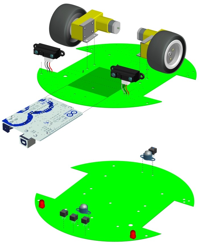
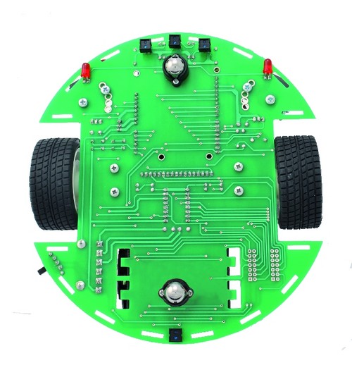
The electronic circuit of the Ardusumo robot is very simple: the core is an Arduino UNO board, interfaced with four sensors – three in front and one on the back- and two Sharp infrared radar. The optical sensors are pointed down and used to follow tracks marked on the ground and recognize when the robot is crossing a delimited border (Figure 2).
 |
|
| Figure 2. | Ardusumo robot is very simple: the core is an Arduino UNO board, interfaced with four sensors – three in front and one on the back- and two Sharp infrared radar. |
Each optical sensor contains a light emitting diode, pointing towards the ground and a detector for reflected light. In this way it can distinguish thanks to light intensity (more light is detected when a more reflective surface is illuminated) the track to follow. The three front sensors are aligned. The middle one follows a track and detect whether the robot it has gone away from it. In that case the microcontroller detects the movement and imparts commands to correct it. The rear sensor is designed to detect when the robot approaches the edge of the ring. In this case, the firmware sends a forward motion command to break the deadlock.
The two infrared radar are pointed forward and slightly tilted sideways. They are the eyes of the robot, used to perceive obstacles and walk around them.
Two LEDs, to illuminate the scene in front of the robot, are interfaced to the Arduino. There’s also a buzzer to give alerts and a dual engines controller used to operate the two geared motors for the traction wheels.
The wheels are placed on the same virtual axis and, by varying the rotation speed, Arduino “steers” the robot.
In the front, a “ball-caster” support serves as the third wheel for balance. A second ball-caster is located on the opposite side and contributes further to balanceing (Figure 3).
 |
|
| Figure 3. | Ardusumo robot chassis construction variant. |
With the same track you can print both: the PCB that hosts all the basic electronics (works as a actual phisical basis) and the four mechanical and electrical connection to the infrared sensors. This in case you decide to mount them.
The Electric Scheme (Figure 4).
 |
|
| Figure 4. | Ardusumo Electric Scheme. |
Ardusumo electronic circuit is based on Arduino: are the connections needed for the contacts on the board are available on side pin-strip. Via D4, D5, D6, D7, D8, D9 and D10, Arduino manages the motors controllers. PWM is used to drive the two motors so they provide traction and rotation to the robot. The robot steers with the same principle used for tanks: by rotating wheels in opposite directions.
The controller is a TB6612FNG: it contains a double PWM bridge driver, controllable by means of a simple logic. Each of the drivers is composed of an output bridge formed by four complementary MOSFET protected by a diode.
Each section of the pilot is controlled with a PWM signal to be applied to PWMA and PWMB lines (respectively channel A and B). That signal that is duplicated identical between M1 and M2. The AIN1 and AIN2 set A bridge operating mode, while BIN1 BIN2 and do the same for the bridge B.
This logic is used to determine the direction of rotation of each motor as well as its arrest. Clockwise rotation (connecting the motor with the polarity indicated in the diagram) is obtained with AIN1 set to high and AIN2 set to low, viceversa motor turns counterclockwise.
Setting AIN1 and AIN2 to logic 1, the motor stops. In this case the two N-channel MOSFETs are in the ON state, short-circuiting the motor.
Of course, other channels follow the same logic.
But let’s proceed with the analysis of the circuit diagram. Arduino‘s RST and A4 lines both link to a different button: P2 calls for reset, while P1 is reserved for custom applications.
The digital D1 line, used as output, pilots the LEDs arranged frontally to the robot. D0 is used to activate the firmware configurable buzzer BZ1.
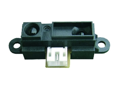
The analog input lines A1 and A0 interface Arduino with the two infrared distance meters which provide an analog signal. This signal is proportional to the distance measured between the sensor and the obstacles faced.
The sensors used for the detection of objects in front of the robot are Sharp GP2D12. The presence of two sensors lets us identify both the distance and the (approximate) position of obstacles: just by crossing data coming from the two sensors (Figure 5).
 |
|
| Figure 5. | Ardusumo Robot Eyes - infrared sensors GP2D120. |
The GP2D12 sensors must be connected to the S1 and S2 connectors, which are connected to A1 and A0 lines. Each connector carries the 5-volt power and the ground, necessary to feed the devices. The “line sensors” are connected to the A2, D2, D3 and D1 lines of Arduino: they catch the analog signals that the sensors provide; each Vishay CNY70 sensor, has a LED and a phototransistor pointed in the same direction.
In this way a near object would reflect the light produced by the emitter diode that is then intercepted from the phototransistor. This effect produces an increase in the reverse saturation current in collector junction of the phototransistor. The closer is the object is, the greater the reflected light, but pay attention to the color of the object. If the surface is white the reflection is greater than that obtained if it’s black. Every CNY70 has the emitter diode polarized directly with a resistor (R8 for T1, R2 for T2, R4 for T3 and R6 for T4). The phototransistor, polarized with the 5 volts on the collector, has the emitter connected to the input line from Arduino and ends to the ground with a resistor.
In this way, on on the emitter of the phototransistor, we have a voltage that is directly proportional to the intensity of the reflected light.
Finally, let’s see the power supply section: it is based almost completely on the Arduino’s circuitry and has a battery pack made up of 6 penlight batteries NiMH batteries (arranged in series , to obtain a nominal voltage of 7.2 volts). The positive and negative wires should be connected to + PWR and – PWR contacts of the base board. For the power supply you can even use six common penlight batteries, in which case we will get 9 volts on the PWR.
After passing the deviator on SW1 and fuse that protects the battery from shorts, the voltage reaches the contact Vin of Arduino, the Vin of the auxiliary connector and the resistive divider formed by R11 and R12. All this brings then the reference potential to A3 contact of Arduino.
Arduino regulator obtains the 5 volts for the on-board logic, and gives the voltage required to operate the entire circuit from his 5V contact . Through A3, Arduino can read the supply voltage and draw conclusions on the basis of the firmware that you will upload.
 |
|
 |
|
| Figure 6. | Arduino Robot chassis board. |
Table 1. BOM
| R1, R3, R5, R7, R11, R12 |
47 kOhm | |
| R2, R4, R8 | 390 Ohm | |
| R9 | 100 Ohm | |
| R10 | 270 Ohm | |
| C1, C2 | 100 nF 63 V | |
| C3, C4, C5, C6 |
470 uF 16 V | |
| C7, C8 | 1 uF 35 V | |
| C9 | 100 uF 35 V | |
| T1, T2, T3, T4 | CNY70 | Optical Reflex Sensors - Vishay |
| P1, P2 | Microswitch | |
| BZ1 | Buzzer | |
| SW1 | Switch | |
| U1 | TB6612FNG | Driver IC for Dual DC motor |
| LD1, LD2 | LED 5 mm | |
| F1 | Fuse 1A | |
| S1, S2 | IR sensor GP2D12 connectors |
Downloads
Firmwares that allow you create a fighter robot - download
