Sean Coates
Sean shows us how to use an Arduino for kegerator temperature control. A Kegerator is a beer keg built inside a refrigerator. Anyone want a cold beer? He discusses the home brewing process and how a microcontroller can be applied to this and many other sensing and control task. Man I’m thirsty now…
I belong to a diverse group of amateurs who have a fascination for brewing our own beer. In addition to the satisfaction of brewing the beer I drink, and the control I have over the process (and the ability to easily avoid crappy mega-swill beer from the big breweries), we homebrewers get to play with a bunch of cool gadgets. Even if you don’t have any interest in cooling beer, this information in this tutorial can be applied to other projects that involve analog sensors, and high-voltage/current devices.
Over the past few months, I’ve started kegging my own beer, at home. This is a pretty simple process, but one of the key ingredients to making consumable draught beer is temperature control. Obviously, beer doesn’t taste quite as good if it’s warm (or too cold, for that matter), but there’s more to it: carbon dioxide is much more soluble in water (or beer) at lower temperatures, so it’s essential that kegs be kept cold, when serving.
Most homebrewers take one of three approaches to cooling their beer: buying a pre-made kegerator, gutting a regular refrigerator to hold kegs with taps on the door, or altering a chest freezer to hold the kegs and mount taps. I chose to take the third approach (a friend was getting rid of a near-perfect sized chest freezer).
Generally, chest freezers have thermostats that work in the “freezer” range. That is, below 0Â ºC, or below water’s freezing point. Even at the “warmest” temperature, most freezers will still freeze beer. This is no good when it comes to kegerators. Many homebrewers solve this problem with a device referred to as a “Johnson,” “Love,” or “Ranco” controller (depending on the brand of controller). Basically, this device plugs between the AC mains and the chest freezer, and has a temperature probe that is placed in the freezer (the freezer’s internal thermostat is set at “maximum cold”). The temperature probe, depending on the model chosen, will either be a solid/liquid mechanical probe (usually found on the cheaper controllers–this is likely the same type as is found on the freezer’s internal controller), or a thermistor.
One day, a few weeks ago, I had the urge to finally get my chest kegerator cooling my beer. Living in Canada has its benefits, but one of the recurring problems we Canadians face is the difficulty (and delay) in having items shipped from the US (where most of these controllers are made/sold). I wanted to get it working now, not in a week, or more, when a controller would arrive. Additionally, these controllers can run for anywhere from $ 60-200. I didn’t feel like waiting, and I didn’t feel like paying. So, what’s a resourceful geek supposed to do? Build your own, of course.
The first thing I did was figure out what components I would need to build my own controller:
- a microcontroller (I had an Arduino NG that I hadn’t embedded in anything, yet–perfect)
- a thermistor (I happened to have some that I picked up from my local electronics shop for $ 1 each. They’re marked 1 K, which usually indicates the resistance at room temperature, or somewhere around 20Â ºC)
- some resistors to create a voltage divider to interface with the thermistor
- a solid state relay (SSR) (again, I happened to have one on hand that I got from my local electronics shop for $ 5. Check eBay, there are plenty of good ones available for good prices). You need to make sure that the SSR can handle the current that your freezer will draw, both when the compressor fires up and draws extra current, and also when it runs at a lower current for longer periods of time.
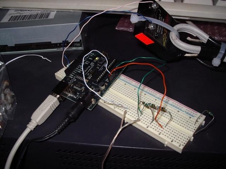
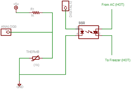
I built my first prototype on a breadboard, shown above. The circuit for this is pretty simple: on the analog side is +5 V, resistance, and analog line, a thermistor and ground. This is best explained by a schematic diagram, shown below
Let’s go through the components listed above. First is the microcontroller. Hopefully everyone reading this site has heard of the Arduino, but in case you haven’t, it’s a simple microcontroller that has a number of analog inputs and digital input/output pins. For this project, we’ll be using one analog pin, one digital pin (in output mode), and the 5 v/ground power bus, as well as some code that we’ll discuss a bit later.
Thermistors are variable resistors, like photo-resistors or potentiometers. Instead of detecting light or some sort of manual adjustment, however, the resistance in a thermistor changes depending on the component’s temperature. My particular thermistors have a range of approximately 0C-100 ºC, where 0 ºC gives a resistance of near 2 K, and around 0 Ohm at 100 ºC (as measured with an analog thermometer). Below 0ºC and above 100 ºC, the thermistor reads closed (no conductivity, or infinite ohms). Yours might be different, so you’ll have to adjust your code and voltage divider if it is.
Basically, the voltage divider part of the circuit translates a resistance (the variable resistance of our thermistor, in this case) into a voltage that can be read on the analog pin of our microcontroller. This allows us to detect the thermistor’s temperature, and convert the analog signal to a digital value.
The solid state relay is an interesting device. It’s a bit like a conventional relay, where a secondary circuit (power to our freezer, in this case) can be completed by the primary circuit (our Arduino’s digital output), in a completely decoupled manner. This is usually done via a LED and a photo-diode plus a MOSFET. In practice, there are four poles: two for the high-voltage/high-current/AC circuit and 2 for the low voltage DC circuit. To trigger the SSR, you simply apply +5 v (you need to get a relay that will trigger at 5 v) and ground to the low voltage side (polarity matters, this is a LED, remember), and it will bridge the high voltage poles, to complete that circuit, and turn on the freezer.
As you saw in the schematic, this circuit is pretty simple. You can get a copy of the code here.
The code is a bit more complicated. I’m a programmer by trade. I don’t usually deal with C, but it’s similar to my development language of choice: PHP. I chose to implement my controller in such a way that would allow modularity. For example, I can plug in different thermistor/divider circuits, and all I need to do is add a new Therm structure. As you can see in the attached code, I also have a ‘’Fermenter'’ controller which, while a bit different, is essentially a copy of the circuit discussed here.
Stepping through the code, the first thing you’ll notice is a number of #define directives to set up some constants. I use these later, mostly to keep track of the state of my controller. You’ll see “struct’s” for both the Thermistor and the Controller objects.
Next is the Arduino’s setup()method. This is initialization code that is run once per execution of the sketch (program) to initialize different bits of data. Here is where we designate the digital pins as OUTPUT , initialize the Serial port (which we’ll use via USB to capture data), and set up the Thermistor and Freezer object parameters.
Without getting into too much detail on these values, the Thermistor base values are calculated, based on real-world data that I captured with a hotplate and a thermometer. I didn’t have the datasheet for my thermistors, so if you happen to be able to pull that data, you’re much better off and can skip the tedious manual testing. I determined the 0ºC value of my thermistor ThermB to be 22500, with per-degree steps of 10.2 (or 102 with the 10x factor I needed to get around Arduino’s poor floating-point performance). Note: most thermistors are not linear like this. Either I got lucky, or my measured range was so small that I didn’t have to resort to logarithmic calculations. This works out well for me, but you’ll need to measure and/or check your own datasheet.
Now that we’re set up properly, the Arduino runs the code within the loop()function, indefinitely. Here’s where we actually measure the current thermistor’s value (checkTemp()toggle() the freezer’s power to the compressor circuit, increment the Freezer’s state timer (mostly for debugging–turning a compressor on and off too quickly is a surefire way to reduce the life of your freezer), and output the data to our initialized Serial port. Then, the processor is instructed to delay() for 1000 ms (you could change this value if you like).
The other functions facilitate the above behavior by determining when to toggle the compressor’s power state, formatting output, and calculating the temperature.
That’s pretty much all there is to the firmware code. I managed to create a powerful, customizable temperature controller, all with parts I happened to have (mostly) laying around my workbench. The most expensive part is obviously the Arduino, but it’s still cheaper than a dedicated controller.
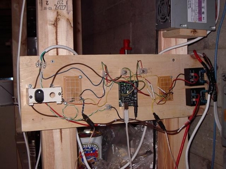
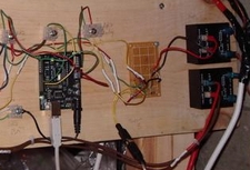
Here is a photo of my current controller in action. The circuit described here is on the right half of the board (I also have a fermentation controller, which you may have noticed in the code listing). Up-to-the-minute temperature logging of my controller can be found here.
