A system that receives its power from a renewable-energy source, such as a photovoltaic panel or a wind-driven generator, typically accumulates power in a rechargeable battery and delivers it to a load. Often, both processes occur simultaneously. Periodic evaluation of the battery's remaining charge ensures extended performance and battery life, as does control of the battery current that goes to the load. A battery's residual charge comprises its previously calculated charge plus the amount of newly accumulated charge or minus the amount of charge it expends. According to Coulomb's Law, you can calculate the accumulated charge as follows:
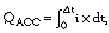
where QACC is the amount of a battery's newly accumulated charge, and i represents the amount of current integrated over time interval Δt.
In its discrete form, the equation becomes
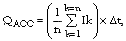
where n represents the number of current measurements, Ik, taken during the time interval, Δt. Although you can select any value for Δt, it's convenient to choose a value equal to one hour, because battery manufacturers specify capacity in units of ampere-hours.
To simplify the microcontroller's firmware and reduce the amount of memory necessary for arithmetic operations, you can divide one hour into 128 measurement cycles and use register shifting to perform the division required in the equation. You calculate each charge measurement as an average value from 32 current samples, which the microprocessor's internal ADC converts. One of the ADC's multiplexed input channels converts charging current, and another converts discharging current. Thus, the equation for remaining battery-charge capacity reduces to QREM=QPREV±QACC, where QREM is the remaining battery charge, QPREV is its previously calculated charge, a plus sign indicates a net charge, and a minus sign indicates a net discharge.
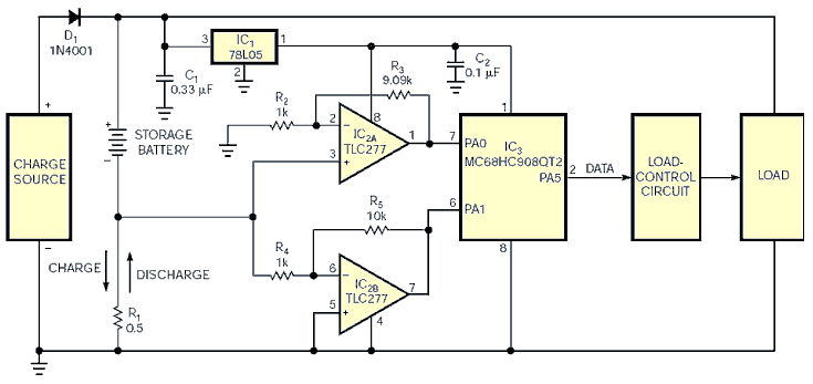
The circuit comprises an eight-pin version Freescale's low-cost MC68HC908QT2 microcontroller, IC3. The voltage across current-sampling resistor R1 reverses polarity depending on whether the battery charges or discharges. Connected as identical-gain noninverting and inverting amplifiers, respectively, IC2A and IC2B sense the voltage developed across R1. Noninverting amplifier IC2A responds only to a positive voltage developed by a charging current and delivers zero output for a negative input voltage developed by a discharge current. Inverting amplifier IC2B responds only to a negative input and delivers 0V for a positive-charging current. The outputs of both op amps are positive and range from 0 to approximately 5 V and simplify design of the interface with the ADC's multiplexed inputs. Using Texas Instruments' TLC277 for IC2 offers the benefits of a small-pc-board footprint and a low input-offset voltage.
You calculate the sense resistor R1's value and the amplifiers' gain, G, by determining the lowest and highest expected charge and discharge currents and applying the following equation:
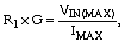
where IMAX is the maximum discharge current and VIN(MAX) is the maximum ADC input. In this example, the maximum charge and discharge currents are approximately 1 A.
Thus, for a 1 A charge or discharge current and a maximum ADC input of 5 V, you can choose a value of 0.5 Ω for R1 and a gain of 10 or 100. Once you calculate the battery's charge capability, you can send the data to a host processor or another destination through a single-wire interface, SPI, I2C, CAN (controller-area-network), or another industry-standard method. To maximize battery life, you can use the microprocessor's output to control current that an external load draws.