fritsl
This is a walk through on how to make an autonomous, self-exploring, "own-mind" (not remote-controlled, not strictly pre-programmed, but reacting to surroundings) robot in a few hours.
It is really easy, and it does not involve knowledge of electronics to get you started with robot-building.
Focus in here is on the absolute necessary to get the basics covered.
This is meant to be an eye-opener, after building this, you can build anything and control any electronic device!
Sounds crazy? It is true, you just need to try it to understand how much power is in some of the chips you can buy for a few bucks today. Welcome to the world of microcontrollers :)
The programming example I write in the end is to make this robot what you would call "wall avoiding" (it will sniff around and explore based on which objects it meets, what is on the left, right and ahead), but it can be programmed into anything - easily. If interest is shown I will provide more programs for it.
Here is another using the exact same basic principles, board, chip etc. it is VERY much alike - Only I have put some more time into this one ;)
Prices are approx. As far as possible, try to get it all from the same shop, and from a shop located in your own country etc to get the best deals and faster deliverance etc.
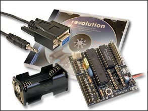
1 PICAXE-28X1 Starter Pack
The 28 pin project board in this package is like a game of Mario Bros; Fun and full of extras and hidden features, making you want to play over and again. This includes the main brain, the PICAXE-28X1.
Price: 60 USD
This is a little expansive, but it is only the first time I recommend you to get this, it includes a lot of nice basic stuff, you get a CD-ROM with lots of manuals, cables, a board, the Microprocessor etc. Actually it is EXTREMELY cheap. Similar packages cost up to 10 times this price!
Be sure to get the USB-version, images in the shops may not match, and show a serial-cable when you are ordering a USB. When buying the USB-version, it is not necessary to get the USB-cable as an extra item, even though it is also sold separately.
Once you have bought this one time, just buy a new board and accomplishing Microcontroller for future projects, much cheaper, you are a Robot-builder with all the basics done.
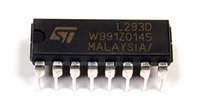
1 L293D Motor Driver
The name says it all, more about this chip later :)
Price: 8 USD
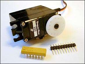
1 PICAXE Servo Upgrade Pack
An easy way to get a servo topped with some small parts needed for this project.
You can also get any standard servo, the pins shown on the image, and a single 330 Ohm resistor instead of the yellow chip, if you should wish.
Price: 30 USD
What is a Servo?
A Servo is a cornerstone in most robotic appliances. To put it short it is a little box with wires to it, and an axle that can turn some 200 degrees. on this axle you can mount a disc or some other peripheral that comes with the servo.
The 3 wires are: 2 for power, and one for signal.
The signal-wire goes to something that controls a servo, in this case that is the microcontroller.
Result is that the microcontroller can decide to where the axle should turn, and this is pretty handy; You can program something to physically move to a certain position.
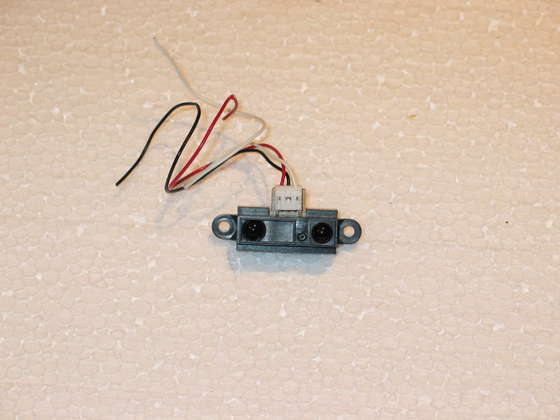
1 Sharp GP2D120 IR Sensor - 11.5" / Analogue
11.5" or another range will do. Only do not buy the "œDigital version" of the Sharp sensors for this kind of project, they do not measure distance as the analogue ones does.
Price: 10 USD
Be sure to get the red/black/white wires for it. This is not allways included, and it is a non-standard socket!
This is actually not a favorite of mine, I usually use ultrasonic sensors, such as the SRF05 (find it anywhere via Google - they also sell it at the picaxe-store picaxe-store where they call it SRF005 and have a picture of the back of an SRF04 in the shop! But it is the right one, and I did tell them but..). Anyway; The SRF05 is much more reliable and precise. It is also faster, but costs a little more, is a little more complicated to write code to, and a little more complex to install - so it is not used here, but if you are fresh, buy one of these instead ;)
If you go for the SRF05, I have made a small walkthrough to connecting the SRF05 here on letsmakerobots.com
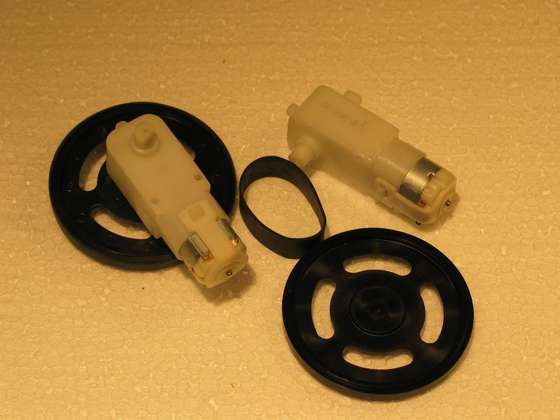
2 Gear Motors with wheels
The higher the ratio, the stronger robot, the lower, the faster robot. I recommend ratio somewhere between 120:1 to 210:1 for this kind of project.
Price, total: 31 USD

You will also need:
- Double sided adhesive tape (for mounting, the foamy sort is best)
- Some wire
- Ordinary adhesive tape (to isolate a cable perhaps)
- Simple soldering equipment (Any cheap kit will do fine)
- An ordinary small nipper or scissor to cut things
- A screwdriver
You could also get, while you're at it:
- Some LED's if you want your robot to be able to signal to the world or make cool flashing-effects
- More servos to make your robot move more..erh..arms? Or servos with servos on etc.
- A tiny speaker if you would like your robot to produce sound-effects and communicate to you
- Some sort of belt-track system. Robots with belt tracks are way cool as well, and the controller and the rest will be the same.
- Any kind of line-sensor-kit, to turn your robot into a Sumo, a Line-follower, stop it from driving off tables, and everything else that needs "a look down".
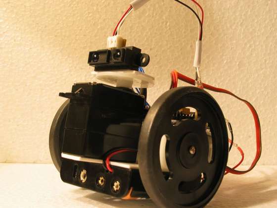
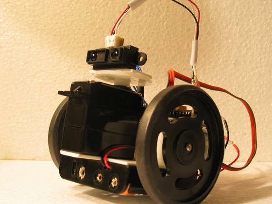
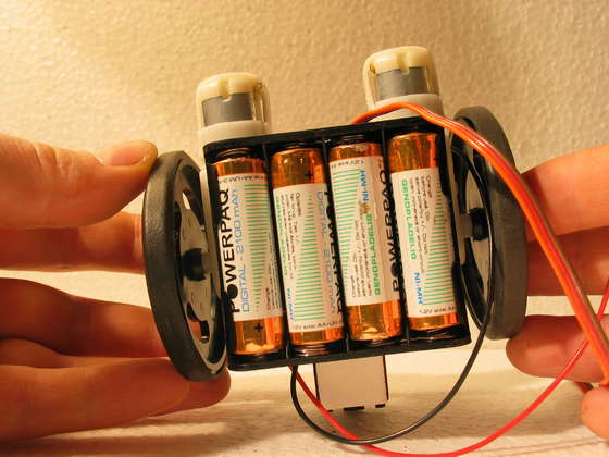
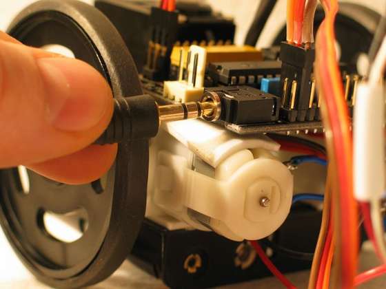
First mount the wheels to your geared motors. And add tires (rubber bands in this case).
An easy way to mount stuff for fast (and amazingly solid and lasting) robots is double adhesive tape
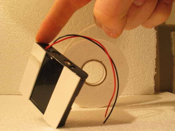
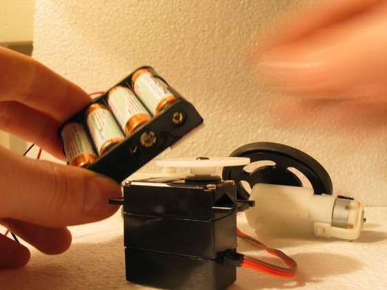
Insert the batteries, so you have a realistic idea of weight and balance.
When batteries are below the axel of the wheels you can make it balance, but it is no problem if it does not.
Add some double adhesive tape to the button of the server as well, and..
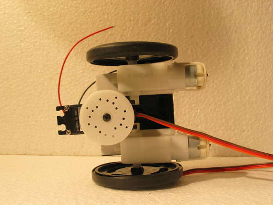
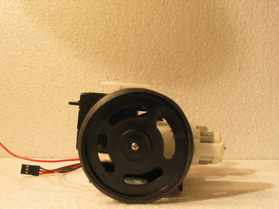
Chose your own design, you can also add extra materials if my “design” is too simple.
Main thing is that we have it all glued together: Batteries, Servo and wheels. And wheels and servo can turn freely, and it can stand on it´s wheels somehow, balancing or not.
Take out the batteries, to avoid burning something unintended!
(trust me, you want to ;)
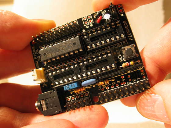
You should have a project board similar to the one on the picture.
Notice that it has a chip in it. Take it out. The chip is a Darlington-driver that is quite handy placed there on the board, but we will not need it for this project, and we need it´s space, so away with that chip!
It is easiest to get chips out of their socket by inserting a normal flat screwdriver just below it, move it ind, and tip up the chip carfully.
A fresh, brand new chip usually do not fit into a socket right away. You will have to press it sideways down on a table, to bend all the legs in an angle so it will fit. (Legs go down, into the sockets :).
Make sure all the legs are in the sockets.
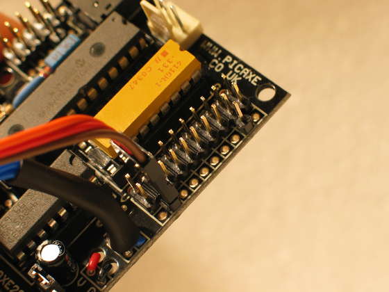
If you bought the Servo upgrade from Picaxe, you have a yellow chip. Put it in place of the Darlington.
Note that not all holes in the project board are filled out with the yellow chip. We only need the eight to the right in the picture, as this is just simple resistors, we do not need to feed them extra.
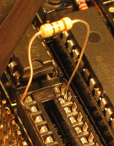
This yellow chip is actually just 8 * 330 Ohm's resistors in a neat package. And so, if you should have a resistor, you can just insert it instead in slot numbered “0” (see picture for this ugly little hack), as this is the only one we will use, when we only use one servo.
Also insert the large chip, the brains, the microcontroller, the Picaxe 28(version number) into the project board.
Important to turn this the right way. Note that there is a little mark in one end, and so on the board. These must go together.
This chip will get power from the board via 2 of it´s legs.
All the remaining 26 legs are connected around on the board, and they will be programmable for you, so you can send current in and out to detect things and control things with the programs you upload into this microcontroller. (cool!)
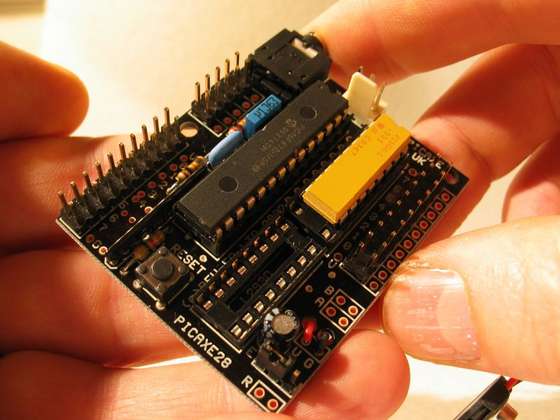
Now insert the L293D motor-controller in the last socket. Be sure to turn this one the right way just as the Microcontroller.
The L293D motor-controller will take 4 of the outputs from the microcontroller, and turn them into 2. Sounds silly? Well.. Any ordinary output from the microcontroller can only be “on” or “off”. So just using these would (example) only make your robot able to drive forward or stop. Not reverse! That may come in unhandy when facing a wall.
The board is made so smart that the 2 (now reversible) outputs get their own space, marked (A) and (B) just next to the motor-controller (Bottom right on the picture). More about this later.
On the backside of the board you may find some strange plastic.
This has no use, it is just a leftover from manufacturing.
They “dip” the board in warm tin, and parts they do not want so get tinned is sealed with this stuff.
Just peal it off when you need the holes they seal.
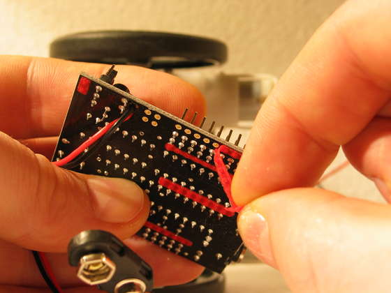
Take 4 pieces of wire, and solder them to the 4 “A & B” - holes.
.. Or if you are that advanced, use some other means of connecting 4 cables to the standard sized holes! (one can buy all sorts of standard sockets and pins that will fit)
If you (like me) just solder onto the board, you can strengthen this part with some tape. or if you have some of that heat-shrinking plastic you can support the wires with this.
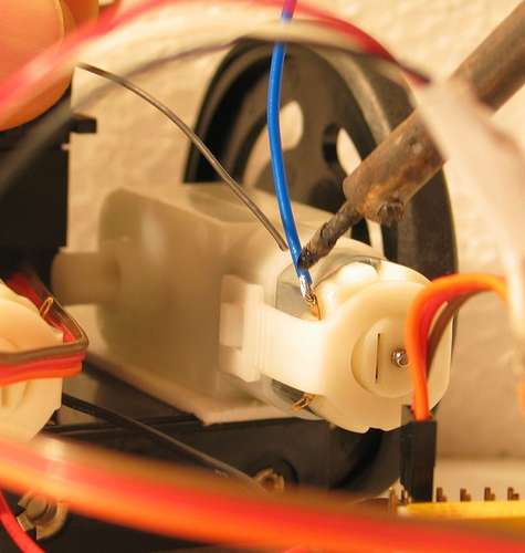
The 2 “A” goes to one motor, and the 2 “B” to the other.
It does not matter which is which, as long as “A” is connected to one motor, and “B” to the two poles of the other.
(yes, my soldering iron is really dirty, I know, haha - as long as it works, you know ;)
Now let´s hook up the servo.
If you should read the Picaxe documentation, you will read that you should use 2 different power-sources if you add servos. To put it short; We don´t mind here, this is a simple robot, and to my experience this works just fine.
Yo will need to solder an extra pin to output “0�, if you want to use the standard servo connection. Such a pin comes with the Picaxe upgrade pack (a whole row, actually), but you only need one for one servo, and they can be bought in any electronics store.
If your servos cable is (Black, Red, White) or (Black, Red, Yellow), the Black should be to the edge of the board. Mine was (Brown, Red, Orange), and so the brown goes to the edge.
The hint is usually the Red; It is what is referred to as V, or any of these, used in random: (“V�, “V+�, “+�, “1�). This is where current comes from.
The black (or brown in my case) is G, or (“G�, “0� or “-�). This is also known as “Ground�, and is where current goes to. (the 2 poles, +/- remember your physics-lessons?)
The last color is then “the signal� (White, Yellow or Orange)
A servo needs both "+ & -" or "V & G", and a signal.
Some other devices may only need "Ground" and "Signal" (G & V), and some may both need V, G, Input and output. Can be confusing in the beginning, and everything is allways named different (like I just did here), but after a while you will get the logic, and it is actually extremely simple - Even I get it now ;)
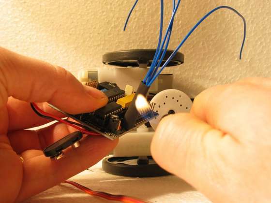
Now let´s hook up “the head”, the Sharp IR-sensor. (or SRF05 if you went for that option)
(If you bought an SRF005 or similar instead, you should look here on how to hook this up, it is different from this!)
There are a million ways to hook up a thing like the Sharp IR-sensor, but here are clues:
Red needs to be connected to V1, that is (in this setup) anything marked “V”, or is connected to this.
Black goes to G, anywhere on the board.
White is to be connected to Analogue input 1.
If you read the documentation that comes with the project-board, you can read how to attach the accompanying ribbon-cable, and use this.
What I have done on the picture, is to cut off a cable from an old burned out servo, soldered in a pin, and connected the whole thing just as a servo. You can use it to see which colors of the Sharp goes to which row on the board.. or one way to do this.
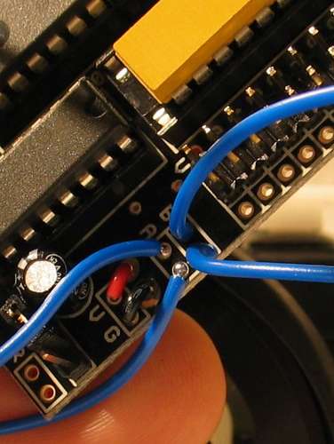
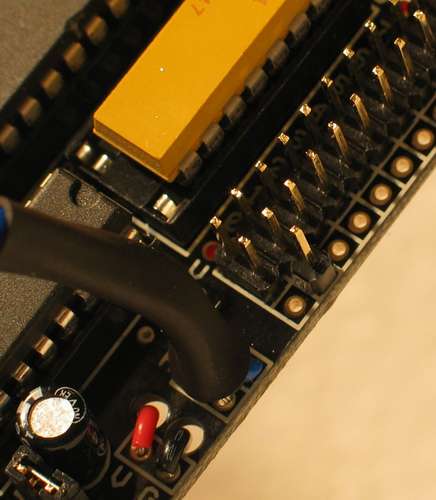
Weather you use the ribbons or “my method” of connecting the Sharp IR, you should also connect the 3 remaining analogue input to V. (look at the little pins connected on the picture, next to the plug)
I had some jumpers laying, and you can see that all 3 connections left are short cut. (The last pair, not touched, are just two “Ground”, no need to short cut these). If you use the ribbon, you can just connect the inputs to V (or ground for that matter) by connecting the wires in pairs.
The reason it is important to shortcut the unused analogue inputs here is that the are “left floating”. This means that you will get all sorts of weird readings where you try to read if these are not connected. (to put it short, this is a semi-fast paced walkthrough, we must get to the end ;)
Now for some fun!
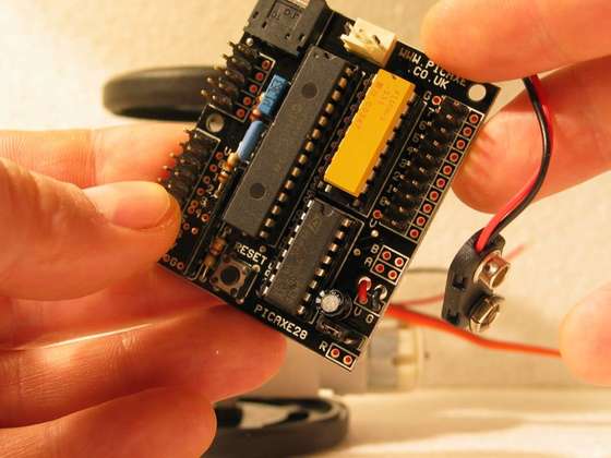
Some how you should get the Red wire from your batteries (+) hooked up to the red wire on the project board (V). And the black (-) to (G).
How you do this depends on the equipment you bought.
If there is a battery-clip on both batteries and board you should still make sure that the "+" from the batteries ends up to the "V" on the board. (Learn more here)
Sometimes (though not often) the clips can be reversed to each other, and just putting two matching clips together is no guarantee that + gets to V and - gets to G! Make sure, or you will se melting things and smoke! Do not feed the board with more than 6V (no 9V batteries, even though the clip fits)
As a note; We are only working with one power-supply here. Later you will want to use same Ground, but both V1 and V2. That way your chips can get one source, and the motors etc another (stronger) voltage.
Install the Picaxe Programming Editor on a PC, follow the manuals to get your Jack / USB / Serial hooked up, Insert the batteries in your (still headless) robot, insert the jack stick in your robot.. enter the programming editor, and write
servo 0, 150
Press F5, wait for the program to transfer, and your servo gives a little yank (or spins, depending on which way it was).
If something goes wrong here, contact mecontact me, or mess with the manuals and ports etc, until no errors are reported, and all seems to work,
To test, try to write
servo 0, 200
and press F5
The servos disc should spin a little and stop. To get back, write:
servo 0, 150
and press F5
Now your robot's “neck” is facing forward.
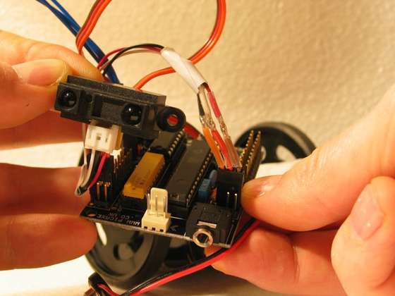
Stick on the “head” - the Sharp IR
You have actually made a robot. Now the fun starts, you can program it to do anything, and attach anything to it, expand in any way. I am sure you are already full of ideas, and you are likely not to have followed me all this way ;)
The design may wary, you may have used other parts etc.. But if you have connected as described, here are some tips to get started programming your robot:
Enter (copy-paste) this code into your editor, and press F5 while the robot is connected:
Note: The code will look a lot nicer once you get it into your editor, it will recognize commands and give them colors.
With some clever programming and tweaking, you can make the robot drive, turn it´s head, make decisions, make small adjustments, turn towards “interesting holesâ€� such as doorways, all working at the same time, while driving. It looks pretty cool if you make the robot spin while the head is turning ;)
Up for some more advanced code? Check this: http://letsmakerobots.com/node/25
Sound:
You can also add a small speaker to example (output) pin 1 & ground, and write
Sound 1, (100, 5)
- or within the example program above make it
Sound 1, (b1,5)
- to get funny sounds depending on the distance to objects ahead.
You could also attach a lamp or LED to pin 2 & ground, and write (remember LED's need to turn the right way around)
High 2
to turn on the lamp, and
Low 2
to turn it off ;)
- How about a Laser-pen, mounted on an extra servo? Then you could make the robot turn the laser around, and turn it on and off, pointing out places..
Add a marker on it (perhaps on a second servo, so it can take it on and off the paper?), and teach it to write the number of times you wave your hand in front of it on a piece of paper.
Turn it into a "cat-get-down-from-the-chair"-guardian-robot, shaking when the cat comes near.
Make it chase another robot (or cat?) You will get into some good chase-routines this way!
Make it seek out the middle of a room
Make it act like a mouse; Freeze if there is movement in sight, and always move close to walls and seek out small gaps to get into.
You could also take an old toy-car apart, take out the electronics in it, save the motors and turning-device in it, and hook up your board, servo and sensor - you will have given life to your vehicle :)
Also try to read some of the documentation, it will make sense now that you got a head start, You can do anything now!
Welcome to a very funny world of homemade robots, there are thousands of sensors and actuators just waiting for you to hook them up and make robots out of them :)
Now take some pictures of your robot, and send them to me at letsmakerobots.com - C ya ;)