Dave Vanden Bout
In an application using a pin-limited microcontroller (MCU), I needed to scan an array of 16 buttons. The technique I used involved a series string of resistors of identical value connected between two bidirectional pins of the MCU.
For simplicity, the example shown uses five resistors to scan four buttons (see the figure). A metal pad is created at each juncture between the resistors. When a person touches one of the metal pads, body capacitance creates an RC circuit that the MCU can sense.
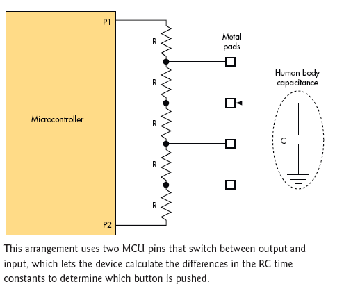
P1 is first configured as an output, and P2 as an input. P1 drives a high level that charges the capacitor through the resistors in the string connecting P1 and the metal pad that’s being touched. In the example, this resistance is 2R. The voltage level on P2 is sensed and the time at which the capacitor reaches a logic 1 is recorded. This time, T2, is proportional to 2R × C. Because P2 is a highimpedance input, the remaining resistors in the string have no appreciable effect on the time constant.
P1 and P2 are then turned into outputs and driven to a low level to dump the charge on the capacitance as quickly as possible. After that, the situation is reversed, with P2 becoming the output and P1 becoming the input. The capacitor charging time, T1, sensed by P1 in this condition, is proportional to 3R × C. The MCU computes the ratio of T1 and T2:
T1/T2 = (3RC)/(2RC) = 3/2.
The ratio is independent of the actual human body capacitance or the resistor value (as long as all the resistor values are identical). The MCU looks for the closest match of the ratio in a table to determine which button was touched.
Assuming a human body capacitance of 100 pF, a value of 10 k? for R gives a time increment of about a microsecond, something most microcontrollers can sense.
As noted, I used this technique to scan as many as 16 buttons. An obvious limiting factor is stray capacitance along the resistor string and on the MCU I/O pins. You also need resistors with well matched values, at least 1% or even 0.1%, depending on how many buttons you are scanning. The MCU pins also have to trigger at the same threshold voltage. If your production environment and MCU allow it, you can use a training session to teach the controller what ratio corresponds to each button and have it stored into the EEPROM or flash.
The resistors in the string serve to attenuate the effects of electrostatic discharge (ESD) when a person touches a bare metal pad connected directly to the circuit. If ESD is a concern, replace the metal pads with pushbuttons that connect a common capacitor to ground. In this case, you can make C larger and reduce R to reduce the effect of stray capacitance.
If an additional pin (P3) is available, you can scan up to 32 buttons by using resistor strings between P1-P2 and P1-P3. With N pins, you could scan 16N(N - 1) buttons.