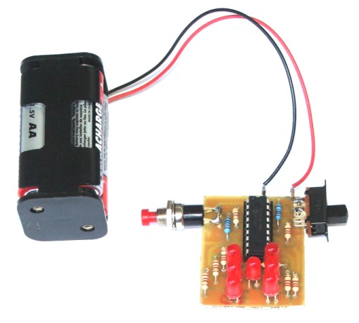
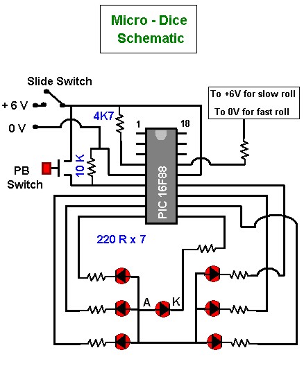
The Micro_Dice is a simple introduction to the PIC microcontroller. This schematic will produce a random number on the led display in a dice pattern. It is simple to construct.. When constructing you can select either fast roll or slow roll option.
|
Component |
Description |
Quantity |
|
Resistor |
220R |
7 |
|
Resistor |
10K |
1 |
|
Resistor |
4K7 |
1 |
|
Slide Switch |
1 |
|
|
Push Button Switch |
1 |
|
|
4 x AA Barrery Holder |
1 |
|
|
AA Batteries |
4 |
|
|
Diode |
LED |
7 |
|
IC Socket |
18 Pin |
1 |
|
Microcontroller |
PIC16F88 |
1 |
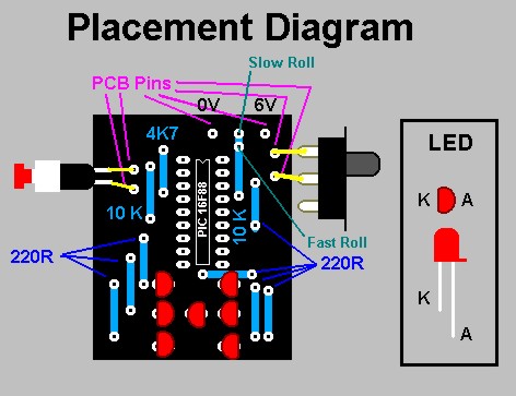
Component Layout
Overview
This is a purely digital circuit and this explanation will the terms high and low. In this project with the 6V source, high will indicate a voltage of 5 to 6 volts and low will indicate a voltage below 1 V. There are no alternate states - digital - it is either high or low.
The PIC16F88 has two input/output registers (PORTA, PORTB). By configuring and reading/writing to them, we can achieve complex electronic results without complex electronic construction. In this project we use all 8 pins of PORTB (pins 6, 7, 8, 9, 10, 11, 12, 13 on the pic) and are labelled PORTB.0 to PORTB.7. PORTB.0 is configured as input to detect the PB switch depress. PORTB.1 to PORTB.7 are connected to the LED's through 220R resistors. The LED's are connected to +6V and are illuminated when the respective pin on PORTB is taken low. The dice pattern is produced by encoding the required pattern as 1's and 0's (1 is off, 0 is on).
PORTB.0 is controlled by the 10K resistor to 0V. This keeps PORTB.0 low while the button is not depressed. When the button is pressed, PORTB.0 is taken high by the switch connected to +6V.
We also use PORTA. PORTA.6 is used to control the fast roll / slow roll option. By selecting if it is connected to 0V or +6Vvia the 10K resistor you can select fast roll or slow roll.
This circuit uses the PIC 16F88's internal clock to eliminate the need for external components. The Master Clear (pin 4) of the PIC is taken high through the 4K7 to eliminate any false resets.
The program
program LED_Dice_decaydim portb_bit as byte
dim porta_bit as byte 'Declare variables dim counter as integer
main:TRISB = %00000001 ' Configure pins of PORTB as output, but pin zero as input
TRISA = %11111111
PORTB = %11111110 'Turn LED's off
' PORTA = %00000000
counter = 1
eloop: 'Start of loop
portb_bit = PORTB.0 'Get button status
if portb_bit = 1 then 'Button press
counter = counter + 1
end if
porta_bit = PORTA.6 'Get fast / slow status
if porta_bit = 1 then 'slow mode
delay_ms(300)
end ifif counter = 7 then 'error handle
counter = 1
end ifselect case counter 'Turn appropriate LED's on
case 1
PORTB = %11101110
case 2
PORTB = %11010110 ' 0 is ON
case 3
PORTB = %11000110
case 4
PORTB = %01010100 ' 1 is OFF
case 5
PORTB = %01000100
case 6
PORTB = %00010000end select
goto eloop ' Stay in loop
end