The project uses 7 RGB LEDs arranged in the form of dice.Each RGB LED has three separate LEDs inside so that makes a total of 21 LEDs and they have been controlled by 4 I/O pins of ATTiny13V Microcontroller.But according to the theory of CharliePlexing,we can only control 12 {n(n-1)} LEDs from 4 I/O Pins.
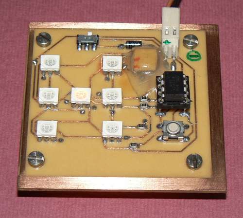
Actually the arrangement of the LEDs in the form of dice is such that they can be divided into four groups.Three having two LEDs each and one having single LED . The LEDs of each group are ON and OFF simultaneously and can be connected to same I/O pins with same enables.In short , they are treated as single LEDs.So that makes total of 4 RGB LEDs to be handled by the code ( 4 × 3 = 12 so charlieplexing holds)'
The 5 I/O pin of the Controller is used for Switch which when pressed generates random numbers from 1 to 6 and when released generates random colours( 6 in all).
The circuit consists of tiny 13 , 7 RGB LEDs ,few resistors and a microswitch apart from power supply connections.
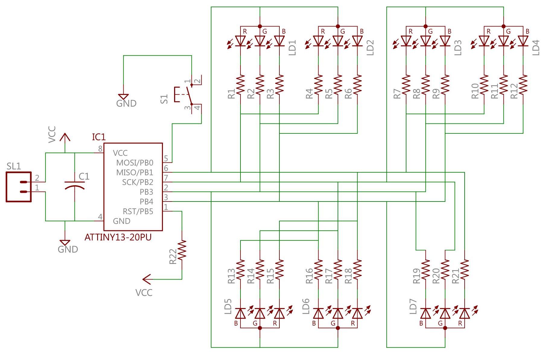
The resistors used in the circuit are in the form of arrays as shown in the image below.
CHARLIEPLEXING
Charlieplexing technique uses all the three possible states : 0,1 or Z ( High Impedance state) of the digital I/O pin of a microcontroller .It manages to control N×(N-1) LEDs using N digital pins. In this technique only one LED can be controlled at a time and hence all the LEDs to be controlled should be refreshed at a suitable frequency so that they appear stationary.
The LED to be controlled at a particular time has its I/O pins (to which it is connected ) declared as output and all other pins are declared as input ( High Impedance or 'Z' state)
Here is the source code of the project written in C language. The compiler used is WINAVR GCC
Makefile and .Hex files are also attached.