Software:
The software is written in a state machine manner. Here are the states: (the state numbers were chosen randomly)
State 1: Show the power up graphics
State 2: Main time/date display
State 50: Main menu
State 60: Set the clock
State 61: Set the alarm
State 62: Set the backlight times
State 63: Set the photo trigger values
State 64: Show the “About this clock” screen
The software was written in C, using the WinAVR distribution of the GNU GCC compiler. (version 3.4.1) Please see http://www.avrfreaks.net/ for tons of good information and examples on using WinAVR. A good place to start in the Graphical Alarm Clock code is the main.c file. From there, you will be able to see the main loop and how the 20 milli second polled loop uses flags and variables to make the software come together in a harmonious end user experience. The makefile is included in the software download. Please note the software is well commented, so to find out the details of the operation you can go through on a line-by-line basis or on a routine by routine basis.
The EEPROM in the microcontroller stores the alarm time, photocell trigger value, backlight on and off-hour. In case if power is lost, these values are pulled out so the user does not have to set them again.
Warning: I put some code in the .h files, which is very bad C structuring.
The Hardware:
The schematic is shown below. Starting in the upper right, power comes in the unit and Q1 is used to protect the IC’s in case the positive and negative terminals are reversed. On the far left side of schematic is the connection to the Optrex LCD. This is a 30 pin, surface mount connector with 0.5mm lead spacing. It was a real bitch to solder down! The AT24C256 was not used in the final clock design. Please note there were several mistakes that I made in the schematic. First, two 10K resistors need to be used to pull-up the RD and WR lines to 5V. Second, a brownout detector needs to be used on the ‘RES line of the LCD. (I used a resistor-capacitor combination along with a diode to keep the ‘RES line low for several hundred milliseconds after power up).
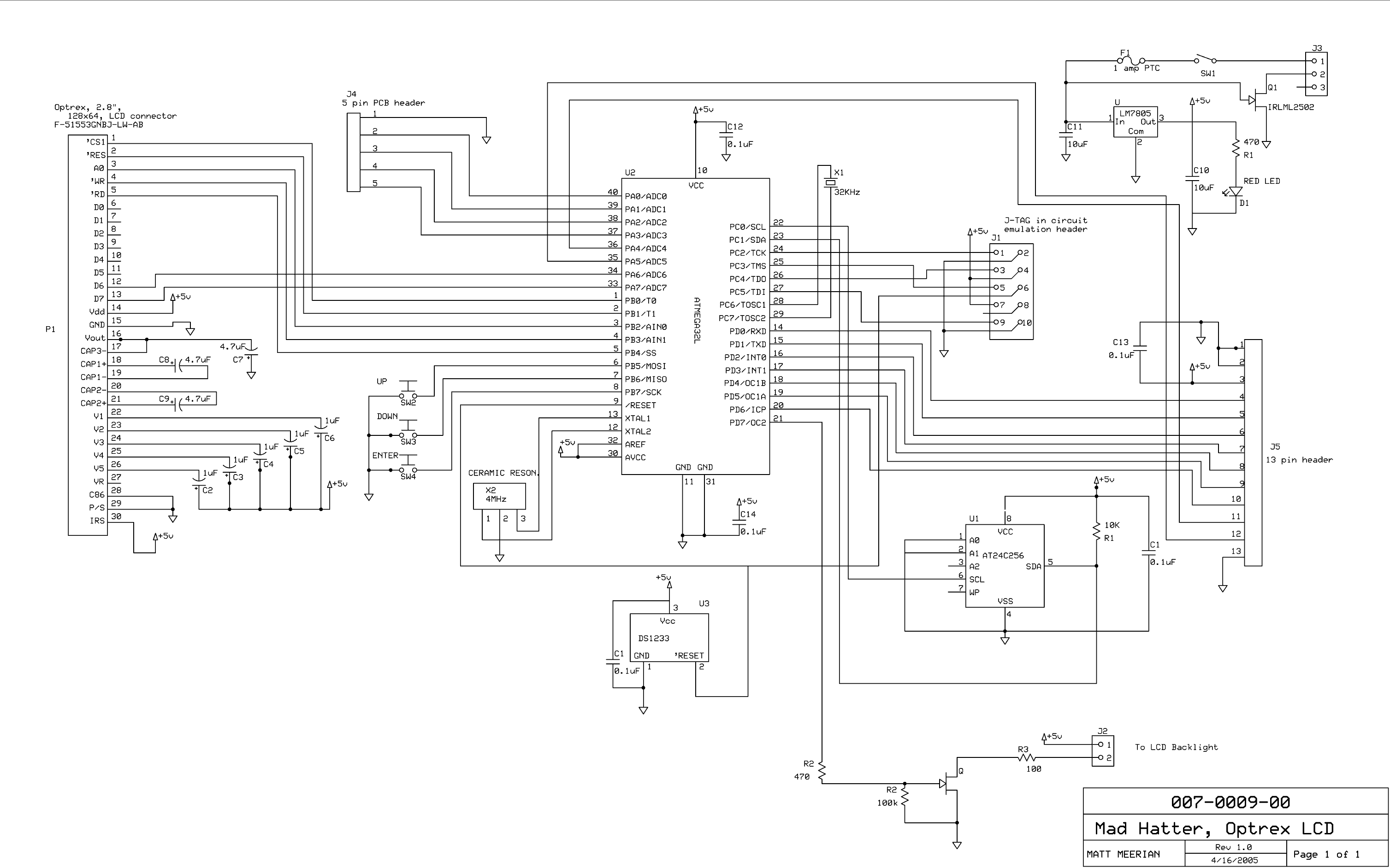
There are several small parts of the design not included on the schematic. The audio output is on the 13 pin header. The 3 user buttons and the photocell is attached to the 5 pin header. See the software comments for more information. The audio buzzer used has an off board NPN transistor to increase the current of the buzzer beyond the 20 or so milliamps an I/O line on the ATMEGA32 can provide.
ExpressPCB was used to create the circuit board. Their miniboard service really works well for the hobbiest’s budget.
The Design Experience:
I had designed the PCB for the F-51553 Optrex display earlier this year. The idea for the alarm clock was hatched on July 6, 2005 according to my engineering logbook. The software, front panel, lexan, testing, pushbuttons and other hardware design concluded on September 1, 2005. The first step and one of the most important ones is the planning of the project. It started with a list of features I would like to see, several hand sketches of the end product, and several loose pages of diagramming out the user interface on paper. From there, I did the nitty-gritty software work and finished up the hardware in last part of August. Testing lasted several nights. The first night, I wrote down about 10 issues that needed to be addressed. The second night had just two issues.
Things I Would Change:
It would be very nice to have a battery backup for the Real Time Clock. Since we tend to loose power on a semi frequent basis, this would have been a handy feature. I used regular laser printer paper for the lexan and then laminated it and stuck it to the front panel using double stick tape. The seams in the double sticky tape can be seen under the paper if you look closely. It would have been nice to use crack and peel paper so there would not have been the tape seams under the paper. Actually, the best front panel would have been from www.frontpanelexpress.com but that would have probably cost about $30 (US). I have order from them and have been very happy with their end product. The software issues I would like to fix is to have the time take up about 7/8 of the screen so it would be easier to see with my glasses off and to have the backlight stay on for about a minute after I exit the menu at night. (So on the main screen, I can verify the alarm is set to on).
Graphical Alarm Clock schematic (PDF format)
Graphical Alarm Clock PCB layout (in Express PCB 5.1.0)
Front Panel Lexan (PDF format, scroll to the bottom of the page)
Graphical Alarm clock source code (WinAVR 3.4.1)