General Description
This is a very interesting project with many practical applications in security and alarm systems for homes, shops and cars. It consists of a set of ultrasonic receiver and transmitter which operate at the same frequency. When something moves in the area covered by the circuit the circuits fine balance is disturbed and the alarm is triggered. The circuit is very sensitive and can be adjusted to reset itself automatically or to stay triggered till it is reset manually after an alarm.
| Technical Specifications - Characteristics | |
| Working voltage | 12V DC |
| Current | 30 mA |
How it Works
As it has already been stated the circuit consists of an ultrasonic transmitter and a receiver both of which work at the same frequency. They use ultrasonic piezoelectric transducers as output and input devices respectively and their frequency of operation is determined by the particular devices in use.
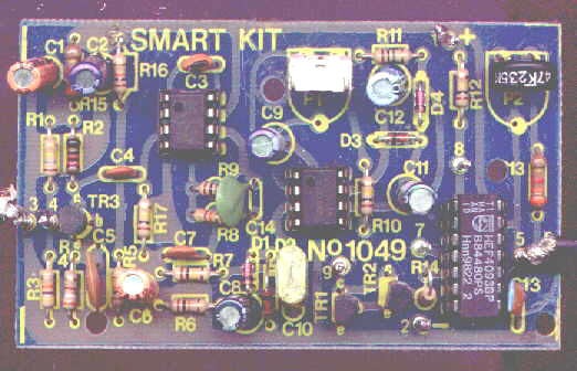
The transmitter is built around two NAND gates of the four found in IC3 which are used here wired as inverters and in the particular circuit they form a multivibrator the output of which drives the transducer. The trimmer P2 adjusts the output frequency of the transmitter and for greater efficiency it should be made the same as the frequency of resonance of the transducers in use. The receiver similarly uses a transducer to receive the signals that are reflected back to it the output of which is amplified by the transistor TR3, and IC1 which is a 741 op-amp. The output of IC1 is taken to the non inverting input of IC2 the amplification factor of which is adjusted by means of P1. The circuit is adjusted in such a way as to stay in balance as long the same as the output frequency of the transmitter. If there is some movement in the area covered by the ultrasonic emission the signal that is reflected back to the receiver becomes distorted and the circuit is thrown out of balance. The output of IC2 changes abruptly and the Schmitt trigger circuit which is built around the remaining two gates in IC3 is triggered. This drives the output transistors TR1,2 which in turn give a signal to the alarm system or if there is a relay connected to the circuit, in series with the collector of TR1, it becomes activated. The circuit works from 9-12 VDC and can be used with batteries or a power supply.
Construction

Adjustments
This kit does not need any adjustments, if you follow the building instructions.
Components
|
|