Magnetic field strength verifier
A simple way of producing a large magnetic field strength is to use a solenoid. The field strength and inductance can be calculated accurately from the physical dimensions and the current. The measured value of the inductance acts as a check on the calculated field strength.
The solenoid is 50 mm long, 16 mm in diameter, and has 200 turns. It is wound on a cardboard former (which will not melt if touched by a soldering iron). The former bore needs to be large enough to accommodate the probe, of course. It can be fitted with a phono connector glued in at one end (hence the need for soldering), so that it can be connected by a shielded cable to the verifier amplifier.
The verifier amplifier is a low-power amplifier using an LM386 operating from a 15 V supply. It is configured as a current-source output to produce a substantially constant current at any frequency from 20 Hz to 100 kHz, with a limited reduction up to 150 kHz.
The verifier schematic is shown in Figure 6.
 |
|
| Figure 6. | Schematic of the verifier and solenoid. |
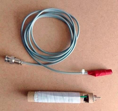
The probe and solenoid are shown in Figure 7.
 |
|
| Figure 7. | Probe and solenoid. |
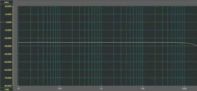
The frequency response of the verifier current output is shown in Figure 8. The magnetic field in the solenoid is, of course, strictly proportional to the current because air has a constant magnetic permeability.
 |
|
| Figure 8. | Frequency response of the verifier current output. |
It would be too much to expect the LM386 audio amplifier to produce 250 mA at 150 kHz and 1000 A/m in the solenoid. It will produce 250 mA up to 15 kHz, 25 mA up to 100 kHz, and 12.5 mA up to 150 kHz. Strong magnetic fields at high frequencies are rarely encountered.
Due to the highly-inductive load, the device gets quite warm when producing 250 mA. A heat sink could be glued onto it if the current needs to be supplied for more than a minute or two, which is normally quite long enough to check the calibration.
Using the verifier
The probe coil is inserted into the solenoid to lie approximately at the halfway point to use the verifier. Moving the probe in and out shows how uniform the magnetic field strength is inside the solenoid; it changes only when the probe is near the end.
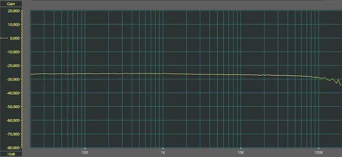
Figure 9 shows the overall frequency response from the verifier to the main amplifier output, with the main amplifier in broadband (11 Hz to 150 kHz) mode.
 |
|
| Figure 9. | Overall frequency response from verifier input to main amplifier output when operated in broadband mode. |
Example use cases for the magnetic field strength meter
With all that in mind, let's explore some example use cases for this magnetic field strength meter.
Magnetic field leakage from a mains transformer
Although mains transformers are being replaced by switch-mode technology, billions are still in use, and for some purposes, they can be preferred. However, they do produce an external magnetic field, and the current is often not sinusoidal because the transformer feeds a rectifier with a filter capacitor. The field thus includes components at harmonics of the power frequency up to at least 10 kHz. This can cause significant ‘spikey hum’ interference in nearby audio circuits. Spikey hum is not a low growl: the harmonic content is exaggerated by the magnetic coupling process, where the induced voltage is proportional to its frequency. It used to be called ‘griddy hum’ in the days of tubes/valves with grids instead of bases or gates.
The magnetic field of a single straight conductor
The magnetic field direction is circular, centered on the conductor, and its strength, H, is accurately given by the formula:
where:
I = the current in amps
r = the radius at which the field strength is measured
Magnetic field leakage from a flat cable (like Romex)
At a distance from the cable, compared with the spacing of the two current-carrying conductors, the magnetic fields from the opposing currents nearly cancel, but close to the cable, they do not. The field strength can be accurately calculated. Figure 10 shows the result of a simplified calculation of the vertical component of the field produced by two conductors 1 cm apart, with the conductors assumed extremely thin. It can be seen that the field strength falls off very rapidly with distance but can be quite strong close to the cable.
 |
|
| Figure 10. | Vertical magnetic field strength between and beyond the very thin conductors of a horizontal two-conductor cable 1 cm apart. |
Measured values of field strength
In the next sections, we'll cover this project's different field strength measurements.
Magnetic field leakage from a mains transformer
At a distance of 25 mm from the enclosure of the transformer, the field strength measured 50 A/m. The waveform was a distorted 50 Hz sine wave. This field strength is plenty large enough to induce an audible ‘spikey hum’ signal in a nearby circuit.
Single straight conductor
The results of a measurement of a long (1 m), straight horizontal conductor carrying 10 A at 50 Hz are given in Table 1.
| Table 1. | A table showing the magnetic field of a long straight conductor | ||||||||||||||||||
|
|||||||||||||||||||
Magnetic field outside a two-conductor cable
Emissions measured at various distances from a horizontal two-conductor cable, with conductors 6 mm apart, are shown in Table 2.
| Table 2. | External vertical field of a 2-conductor cable | ||||||||||||||||||
|
|||||||||||||||||||
The cable carried the current of a 400 W resistive load dimmed to half current. The result cannot be compared numerically with Figure 9 because the conductors' diameter (1.6 mm) is not small compared with their spacing. However, Table 2 shows how the field strength decreases with distance.
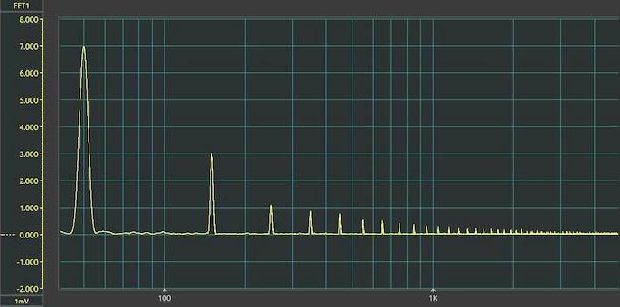
Figure 11 shows the spectrum of the field in terms of voltage with the 50 Hz component at 7 mV, corresponding to 7 A/m.
 |
|
| Figure 11. | Vertical magnetic field outside a 2-conductor cable, linear scale. |
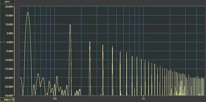
Figure 12 shows the same response in dB (mV), decibels referred to as 1 mV, to highlight the strengths of the higher-frequency components much better. Here we can see that the 150 Hz component is 7 dB below the 50 Hz fundamental, a ratio of 0.45. The harmonics actually extend up to about 10 MHz, but the spectrum analyzer will not extend to such frequencies.
 |
|
| Figure 12. | Vertical magnetic field outside a 2-conductor cable, log scale. |
Field strength meter prototype summary
The two complete prototypes have been built on a plugboard with higher strays than printed boards. The performance of printed boards would likely be a little better.
Schematics
Schematics have been produced using the free and very powerful simulator LTspice, with which I have no connection beyond being a satisfied user. They are reproduced as graphics, which will not run for simulation. The results of simulations are based on somewhat idealized parts with exact values. Component tolerances can affect the mid-frequency gain a little and cause gain variations at the extremes of the frequency response. While these could be corrected by adding several preset components, the verifier makes this unnecessary.
Frequency responses and spectra
The frequency responses and spectra are actual measurements captured and plotted using an affordable add-on for a PC, the Instrustar USB Oscilloscope ISD205C. Again, I am simply a satisfied user. The user interface does need a bit of learning.
