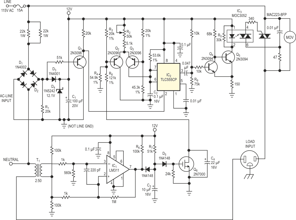
The control circuit in Figure 1 senses a given load and automatically soft-starts the load by synchronously adjusting the power to that load. You can also manually adjust the power delivered to the load by controlling the phase angle of the line voltage across the load. The phase-angle adjustment for every ac half cycle covers 0 to 180°. When the isolation transformer, T1, senses the load current in the ac ground return, IC1’s output changes state, driving the signal diode, D5, into and out of conduction. R6, R7, and C3 create a delay such that the voltage at Q6’s gate decays slowly to allow for the load's switch-closure noise or missed ac cycles. Once Q6 turns off, the voltage at the base of Q2 rises to a higher reference level, which voltage divider R3 and R4 sets. The bias current of transistor pair Q2 and Q3 slowly passes through Q3 as the differential input voltage across Q2 and Q3 changes according to the time constant of R8 and C4. The additional current that Q3 sources to C2 increases the voltage rate of change at pins 6 and 7 of IC2. IC2, a TLC555CP, is a low-power timer configured as a monostable multivibrator.
 |
|
| Figure 1. | This soft-start circuit protects the load from large inrush currents. |
In the monostable mode, the timer issues a positive pulse output every time a negative-going trigger pulse arrives at Pin 2 of IC2. The output pulse width corresponds to the time it takes the voltage on capacitor C2 to ramp from 0 V to 2/3 VCC. With a constant current essentially charging C2, the charging is linear, and the output at IC2’s Pin 3 is proportional to the current set by R2. The full-wave bridge, with D3 and D4 and filter capacitor C1, forms a dc power supply for the timer/controller. The common cathode node for D1 and D2 pulls to ground via R1 every time the line voltage approaches 0 V. Q1 turns on and supplies a negative-going trigger to Pin 2 of IC2. This pulse uses its negative edge to provide a minimum pulse width of 200 µsec to the base of Q4. The feedback pair Q4 and Q5 provides signal inversion and limits the current drawn from the 12 V supply rail through IC3. When sufficient LED current develops, the MOC3052 triac driver latches on and generates a gate current in the power triac, triggering it into the conducting state. Once the power triac latches on, the triac driver enters its off state, even if the LED current still exists.
 |
|
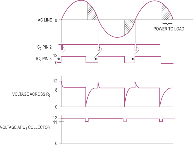
| Figure 2. | The circuit in Figure 1 provides soft-starting by adjusting the phase angle of the power applied to the load. |
The power triac's gate voltage falls below the optocoupler's threshold and cannot hold the optocoupler. The longer the phase delay from the zero-crossing trigger, the smaller the conduction angle and power delivered to the load. R5 facilitates on-off switching of the triac-driver LED by providing a path for leakage currents. Potentiometer R2 provides variable power to the load (to provide motor-speed control, for example). R2 varies the dc-source current that charges C2 every ac half-cycle. Note that the signal ground with respect to earth ground is floating; you must not tie these grounds together. The design in Figure 1 has successfully controlled fans and high-amperage universal motors (100 mA to 11 A). One example is a router for woodworking. By soft-starting these high-torque motors, the reaction torque (to the input current) that the user feels disappears. Moreover, other soft-start designs need two switches. The design in Figure 1 needs only one on-off switch (located at the load). Thus, less danger exists for incurring an accidental starting condition. Figure 2 shows some of the waveforms associated with the circuit in Figure 1. T1 is a signal transformer that you can modify by wrapping two turns of 14-gauge wire around the bobbin to act as the primary winding.
