An obstacle detection unit is an essential part of a variety of projects, such as robotics and security applications. The infrared sensors are widely used for these types of applications. The main drawback of some circuit designs is that the detection units are sensitive to the outside lights and react unstable or noisy.
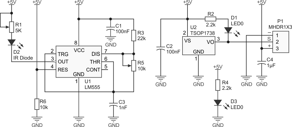
In this project, we selected a proper IR receiving component and designed the circuit in a way to act as stable as possible (Figure 1). Also, you can adjust the sensitivity of the sensor to detect the obstacles located near or far from the sensor.
 |
|
| Figure 1. | Schematic diagram of the IR obstacle detector. |
According to the TSOP1738 datasheet: “The TSOP17XX – series are miniaturized receivers for infrared remote control systems. PIN diode and preamplifier are assembled on lead frame, the epoxy package is designed as IR filter. The demodulated output signal can directly be decoded by a microprocessor. TSOP17XX is the standard IR remote control receiver series, supporting all major transmission codes.”
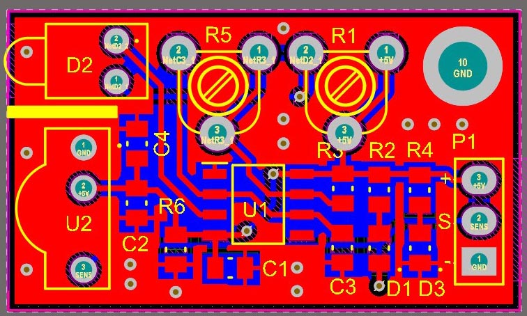
So these features, especially its embedded IR filter, make it suitable for our application. The Figure 2 shows the designed PCB for the circuit. The PCB board mostly designed by SMD components which only take a small 3.2 cm × 1.8 cm board size.
 |
|
| Figure 2. | PCB board design of the IR obstacle detection circuit. |
As you can see on the PCB silkscreen, you must install an isolation barrier between the IR diode and the receiver. The two components are installed next to each other, so you have to make sure that the receiver only reacts to the “front-reflected” IR light.
If you could not find something to put between the sensors, just cover the 5 mm IR diode with a black heat-shrink and allow the light to exit just from the front.
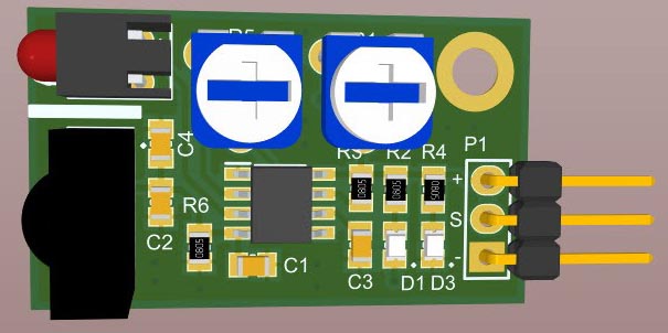
The Figure 3 demonstrate a 3D view of the assembled board. You can inspect the installed components.
 |
|
| Figure 3. | A 3D view of the PCB board. |
LED D3 shows the correct power connection and the LED D1 lights up when an obstacle is located in the sensor detection range.
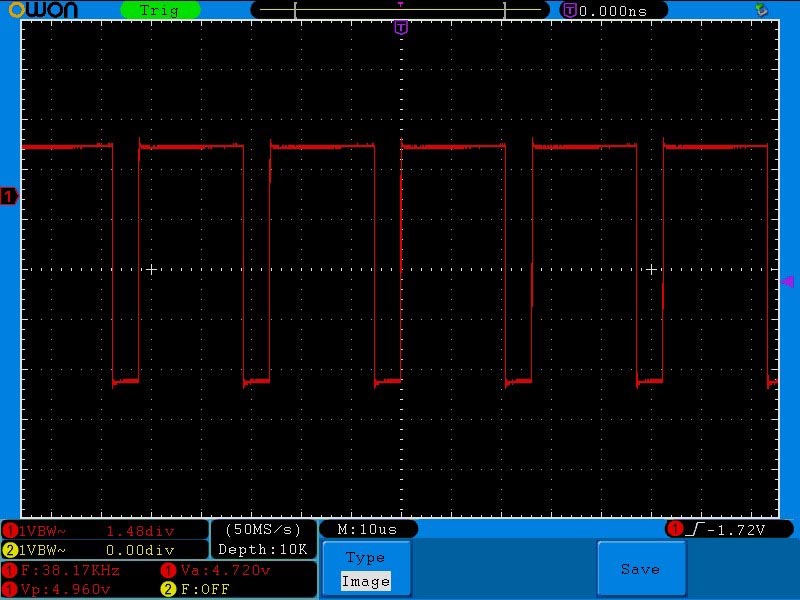
The R1 potentiometer determines the transmission power which of course affects the detection range. The potentiometer R5 adjust the frequency. If you have an oscilloscope, you should be able to see a signal like the Figure 4 at the U1, pin-3 (output). Adjust the R5 to read 38 kHz. Actually, the R5 allows you to install a wide range of similar IR receivers that might operate with different frequencies.
 |
|
| Figure 4. | The 38 kHz signal at the 555’s pin-3. |
A 3-pins male pin-header connects the board to an external circuit. You must connect the +5 V supply to the + terminal and the ground to the – terminal. The “S” output acts as an active low trigger. It means when the sensor detects an object, the “S” output will be connected to the ground (as the LED D3 lights up). The SMD package of the SMD components is 0805.
