Accelerometers are used in instrumentation applications to measure a change in velocity with respect to time or an inclination (the angle between an object’s vertical axis and a line perpendicular to a plane tangent to the earth’s surface). Inclination measurements can be thought of as “dc” or steady-state measurements. Acceleration can also theoretically be steady state. But in real-world applications, it’s generally a short-term transitory phenomenon.
In these short-term acceleration applications, a piezo-bender or piezo film sensor is the transducer of choice. A piezo transducer’s equivalent circuit is an ac voltage source in series with a capacitor. (Other reactive elements contribute second-order effects that are not material to this analysis.) The typical capacitance ranges from a few hundred picofarads to several nanofarads. This capacitive coupling of the voltage source explains why the device cannot provide steady-state inclination measurements.
The equivalent capacitance combines with the input or shunting resistance of subsequent amplifying or buffering circuitry to create a single-pole high-pass filter (HPF). For best results, the higher the shunt resistance, the longer the time constant of the HPF’s pole. This means that longer periods of acceleration can be measured before the time-constant effects degrade the measurement.
The figure shows a practical application circuit. For the prototype, the piezo film sensor, X1, was a Measurement Specialties LDTM-028K. This device already has a small weight attached at one end, and more mass was added to increase sensitivity.
 |
| The piezo device used in the accelerometer has a small weight attached to sense acceleration. More mass was added to increase sensitivity. |
R1 connects the sensor to the non-inverting input of op-amp U1. The resistor prevents damage to the op-amp input from overvoltage, which can occur if the sensor is subjected to very high acceleration (for example, a whack). R1 can also be used to decrease the amplitude of the signal from X1. Based on availability, a resistance of 1 GΩ was chosen. With such a large value, U1 must have very low bias or leakage current, preferably on the order of 1 pA.
R2 is the input shunt resistor through which the 1 pA of leakage current flows. Its value is also 1 GΩ, resulting in an offset voltage of 1 mV (in addition to whatever the op amp’s actual offset voltage is). R2 connects to a 2.5-V reference voltage that sets the op amp’s quiescent output voltage. The reference voltage is derived from U2, an ISL21080, an ISL60002, or a similar reference device.
The op amp is an ISL28158 (or any other very low-input-bias/leakage current device). It is powered from +5 V dc. R3 and R4 set the dc gain, which is +2 V/V in this circuit. A 1-µF capacitor, C3, creates a low-pass filter, which minimizes the circuit’s response to higher-frequency vibration. Film-type capacitors are preferred here as ceramic capacitors may introduce additional undesirable piezo effects (a.k.a., microphonics). If additional low-pass filtering is needed, an additional pole can be added at the op amp’s output as shown by R5 and C4.
Mount X1 on a circuit board so the weight is hanging below the board and the sensor can flex in the direction of the acceleration to be measured. Adjust R1 downward to increase sensitivity. Adjust C3 and C4 to affect the low-pass filters’ time constants.
The piezo device used in the accelerometer has a small weight attached to sense acceleration. More mass was added to increase sensitivity.
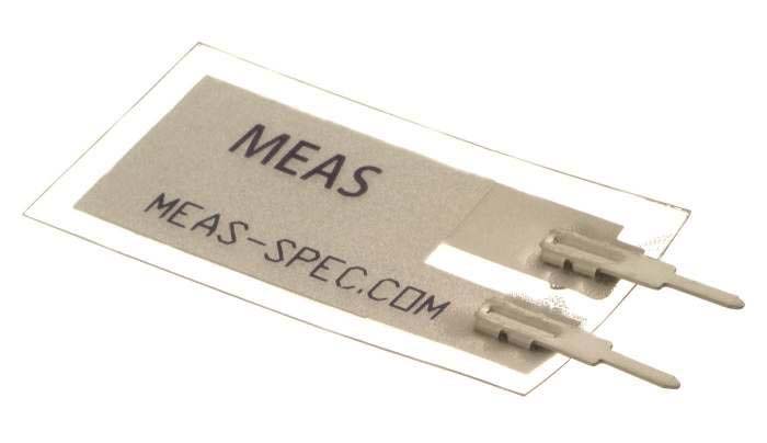
| The sensor without additional weight | The sensor with a small weight attached |
 |
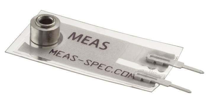 |
| LDT0-028K | LDTM-028K |