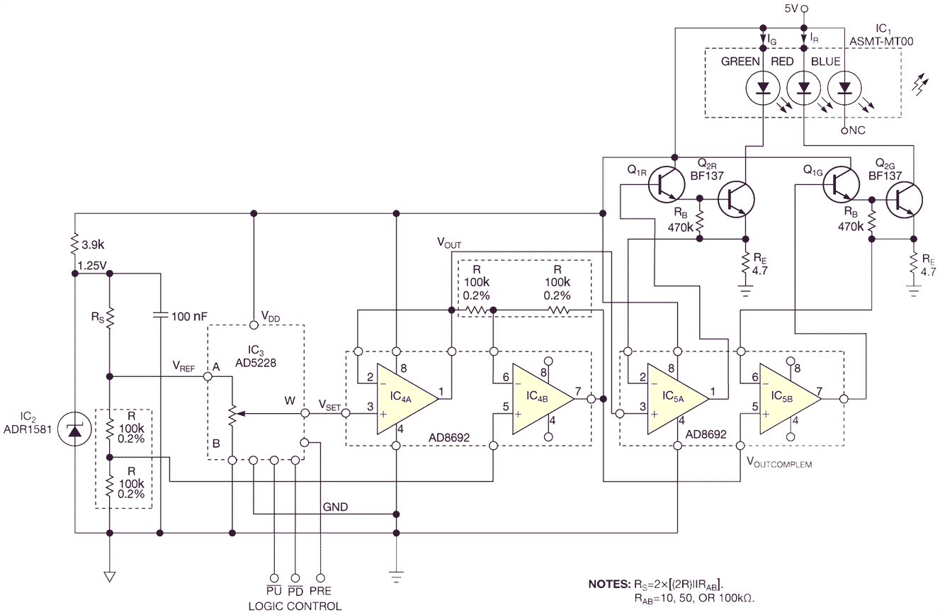
By varying the current through red and green LEDs, you can vary the hue in 32 steps.
The circuit in Figure 1, which lets you create light of 32 of hues, uses red and green LEDs. A constant current divides into two components. One component flows through a red LED, and another one flows through a green LED. You can vary the current from 0 to 100% through the red LED, and thus you simultaneously vary the current through the green LED as a slave-type complement to 100%. When this scenario happens, your eye perceives the resulting light mixture as any hue between red and green. Roughly speaking, the transition from red to green passes through orange, amber, and yellow. You can set any of the 32 hues between red and green, passing through orange, amber, and yellow.
 Click to enlarge |
| Figure 1. This circuit lets you set one of 32 of hues between red and green using a short-term grounding of the pullup or pulldown control pins. |
IC3, an Analog Devices AD5228 resistive DAC, has one-in-32 resolution, and it thus sets the resolution of this circuit. In this application, the resistive DAC functions as a digital potentiometer. You can manually set its wiper position through short-term grounding of its  pullup and
  pulldown control pins. The resistive DAC has no memory, so you have to make this setting after each power-on.
Holding the and pins to a logic low, the wiper position increments or decrements with an increased speed of one step per 0.25 sec, so the output light’s color varies stepwise for a low pullup (Figure 2). You can also preset the hue of the LED, which appears at power-on. For a high Preset, the color is 100% red when you apply power. At a low Preset, a midposition is preset at the resistive DAC and thus the color at power-on is 50% red and 50% green; you perceive it as yellow.
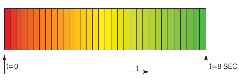 |
| Figure 2. The light output changes quasicontinually from red to green within approximately 8 seconds, using long-term grounding of the pullup pin or a continuous grounding of the pin at power-on. |
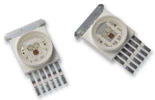
The circuit uses two LEDs in IC1, a high-performance, tricolor ASMT-MT00 LED (Figure 3) from Avago Technologies. The blue LED remains unused. You can, however, connect any of the remaining five red/green, red/blue, blue/red, green/blue, or blue/green combinations instead of the green/red combination this circuit uses.
|
|
| Figure 3. High-performance, tricolor LED ASMT-MT00. |
Although the sum of currents flowing through the red and green LEDs is approximately one-fourth of the nominal per-LED current, the radiance is high, and you should not look directly at the lid of IC1 when it is on from a distance of less than approximately 1 foot.
IC2, IC3, and IC4 comprise a low-side source of two complementary analog voltages (Reference 1). The resistive DAC replaces the classic potentiometer in the earlier Design Idea. These complementary analog voltages are the input voltages for the two power stages comprising transistor Q1 and midrangepower transistor Q2.
The power stage—voltage-to-current converters you make by cascading two bipolar transistors and an op amp— drives each of the two LEDs. The circuit senses output current at resistor RE. The RB resistors eliminate the leakage currents of both bipolar transistors in the cascaded series. These power stages would be functional even with one bipolar transistor instead of two. The cascaded bipolar transistors provide precision in the voltage-to-current converter. With a single power transistor, the relative error would be approximately 1/β, whereas using the cascaded series, the error is approximately 1/(β1β2), where β1 and β2, the current gains of the bipolar transistors, are approximately 300 and 100, respectively. The error results from the current flowing through resistor RE, which is the sum of the output current and the base current of transistor Q1.
You can use this circuit in industries ranging from entertainment to toys; it may eventually find use in experimental psychology and in modern fine arts, which involves the use of optoelectronics.
Holding low and feeding a 50% duty cycle, 0.05-Hz-frequency logic waveform to the pin produces a slow, periodic, quasicontinuous “waving” of the color from red to green and back.
Reference
Stofka, Marian, “Amplifiers deliver accurate complementary voltages”, EDN, Sept 23, 2010, pg 44.