Ivailo Vasilev
Features
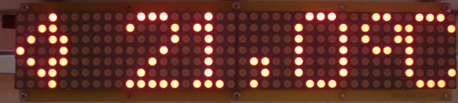
- LED dot matrix display 40×7;
- Display of clock, calendar, inside and outside temperature, text messages;
- Automatic Daylight Savings Time;
- Capability of keeping the real time clock working correctly for more than one week without power supply;
- Inside temperature measurement (0 ÷ +75) °C, ±0.5 °C accuracy;
- Outside temperature measurement (-40 ÷ +75) °C, ±0.5 °C accuracy;
- Supports static and running messages with different effects;
- Full Cyrillic and special symbols supports;
- Memory for 10 messages, each including up to 250 symbols;
- Automatic brightness control;
- IR remote control for settings messages select;
- Power supply: 12 ÷ 24V DC;
- Front panel dimensions 305×69 mm.
Schematic description
| Schematic led control board |
Download schematic in PDF format ![]()
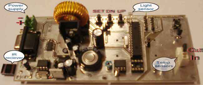
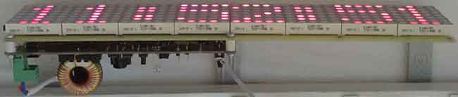
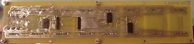
The device comprises two parts: LED control board and LED display board. The two PCBs are designed to fit together one behind the other using two sets of dual row connectors and 4 spacers. One of this connector is used for the electrical connections, while the other is only used as a mechanical connecting element.
The core of the device is microcontroller PIC18F252 (U9). It controls all the functions of the device, generates the overall algorithm to control the LED matrix. LEDs are connected in matrix 40×7. The columns tie together the cathodes of the LEDs and rows tie the LEDs anodes. The LED matrix is controlled dynamically in row by row. To safe space and number of components, the LEDs are driven with specialized LED driver STP16CP05 (U101-U103), produced by ST Microelectronics.
Each of these IC contain 16-bit serial-in, parallel-out shift register, latch register and 16 constant current output channels. Outputs are open drain type, allowing connection of a load supplied with up to 20V supply voltage. The constant current for all outputs varies from 5 to 100 mA and is set from an external resistor (R115-R117). In this application, the three LED drivers are connected in a cascade and controlled from the microcontroller over SPI protocol. The microcontroller sends a 48-bit word, controlling one row at the time. The 40 LSB represent LED states (1-On, 0-Off) in the row and control their cathodes. The 7 MSB control the anodes through the 7 driver transistors (VT101 - VT107). The 40th bit remains unused. The microcontroller sends the 48-bit word every 1 ms.
There are 7 cycles to display each row plus an extra blank cycle, used to process temperature measurements. Thus, the refresh rate of the display is 125Hz. To control the display brightness is used the "outputs enable" (OE) pin. Each row cycle begins with logical 0 on the OE pin (outputs are enabled). The duration of an enabled signal changes depending on the desired brightness, using the microcontroller's on-chip PWM module.
You should note that numbers of columns and rows are not sequential to the corresponding pins of the ICs (U101-U103). This aims to simplify the design of PCB. The LEDs' corresponding bits are rearranged by software to fit with their physical order.
| Schematic led display board |
Download schematic in PDF format ![]()
Real-time clock / calendar
The real time clock is implemented with U10 - PCF8583. This is a clock / calendar / alarm circuit with I2C interface and on-chip 32768Hz oscillator. The PCF8583 contains all necessary counter registers to provide real time clock and date information. Its power consumption is very low (typical supply current is 10µA). It operates in wide range of supply voltage from 1 to 6V. These features will make it possible to have a real time clock available for a long time using a small lithium battery or even a back-up capacitor. The designed PCB provides both options.
The footprint for lithium battery is suited for 2032 type socket. The experiments using 1F backup capacitor show that the clock remains active more than a week after turning-off the power supply. The diodes VD10, VD11 and VD12 should be Shotkey type as shown in the scheme because of their low drop forward voltage. Trimmer-capacitor C21 is used to adjust the oscillator frequency at 32768Hz. For I2C communication is used the Master Synchronous Serial Port (MSSP) module in PIC18F252. This module is set in I2C master mode. On the same bus an external EEPROM (U11) can be connected to expand the capacity of the data storage. The present version of firmware does not need an external EEPROM, so it can be omitted.
Temperature measurement
For ambient temperature measurement are used LM35 sensors (U5, U6). They are factory calibrated directly in ° Celsius. The output response is 10mV/°C. The supply voltage should be between 4 and 30 Volts. To make a full-range temperature measurement, a negative voltage must be applied to the output through a resistor (R4 and R5). To ensure this requirement, the ground pins of the sensors are connected to the analog ground through two diodes (VD4,VD5 and VD6,VD7), which pick them up with approximately 1,4V.
In that case the Vcc (+5V) power supply is not enough for LM35, so additional voltage regulator U1 (78L09) is needed to be used. The signal from the sensor is taken between the output and the negative pins of the LM35. The voltage between these two pins is bipolar with polarity depending on the measured the temperature sign. The sensors could be connected with external three-wire cables. Software is designed to show inside temperature from U6 and outside temperature from U5.
A/D converter
Both LM35's outputs are connected to U4 - MCP3302. This is a Successive Approximation Register (SAR) analog to digital converter. It provides 13 bits resolution (12 bits plus one sign bit). The MCP3302 has 4 analog inputs, which can be configured either as 4 single ended or as 2 differential inputs. The application requires 2 differential inputs to convert both bipolar voltages from the LM35 temperature sensors. As a reference voltage is used U7 - LM336-2,5.
Its output value needs to be adjusted at 2,55V using a trimmer-potentiometer RP1. VD8 and VD9 are used for temperature compensation. The MCP3302 has an SPI interface, using four signal lines. These lines are under software control from the microcontroller (U9). To ensure accuracy the analog ground is separated from the digital using small ferrite beam (L6). This is an SMD type Z600 ferrite beam in 0805 package. The same type is used to decouple the power supply for A/D converter and for temperature sensors and reference voltage (L4 and L5 respectively).
Brightness control
For an automatic brightness control is used a light-to-voltage converter - U8 (TSL257). Its output voltage is directly proportional to the light intensity on the built in photodiode. The voltage from the light sensor is measured using an on-chip microcontroller ADC. The ADC value affects the PWM module from where the LED panel changes its brightness. To avoid unwanted blinks of the display, a slight software delay of the PWM control is applied.
Display functions
The display settings are adjusted from the user with three local buttons S1-S3. The meaning of these buttons is as follows:
- S1 - UP;
- S2 - DOWN;
- S3 - SET.
Clock settings
To enter in settings mode press once SET button. A "Settings" label appeared on display. To set the clock and date, press UP or DOWN buttons to select "Set time". Press the SET button again and display will show the current time, where the hours' digits are blinking. Use UP/DOWN buttons to adjust the correct hours. Then press SET to select minutes. After the minutes are set, the display will switch to date adjustment. Adjust date, month and year and press SET to finish. The software automatically calculates the day of the week.
If an incorrect date is selected (for example 29.02.10), the display will show an "ERROR" message for a while and will return at the beginning of the date adjustment. When the date is set correctly the display will show a new set clock with blinking "OK" and will wait to confirm the new clock/date values. If the UP button is pressed again the display will ignore the new values and returns at "Settings" mode. If the DOWN button is pressed the display will return at the first step of the "Set time" procedure. When the button SET is pressed a new clock and date value are accepted, seconds are reset and display will run in normal mode. The software automatically switches on Daylight Savings Time (+1 hour). It happens on the last Sunday in March, at 3:00 o'clock a.m. Return to winter-time (-1 hour) is done on the last Sunday in October, at 4:00 o'clock a.m.
To be continued