Ivailo Vasilev
Brightness settings
The user can select the brightness level in 8 steps or select an auto mode. To change the brightness from "Settings" menu, select Bright and press SET. The display will show the current bright level (from "Bright 1" to "Bright 8") or "Bright A" for auto mode. The desired value is selected by pressing the buttons UP and DOWN. When the SET button is pressed again, the selected value will accept and store it in EEPROM. To exit from "Settings" menu and return in normal mode of display press SET button, when a label "Settings" appears.
IR remote control
An additional feature of the device is the possibility to change settings using an Infrared remote control. It allows the device to be installed on a place with difficult access. The decoder is implemented with microcontroller PIC12F675 (U52) and designed to work with a standard TV remote control, matching RC5 protocol. This protocol is supported from TV Philips.
The decoder received a demodulated digital signal from IR receiver TSOP1736. The software decodes the received command and transmits it to the main microcontroller U9 over an asynchronous serial connection. The LED VD51 blinks once at each recognized command. The main microcontroller (PIC18F252) receives commands from IR decoder using its hardware Universal Synchronous Asynchronous Receiver Transmitter (USART) module. Because the same module is also used for a RS232 connection to the PC, the RX signal is multiplexed between the U52 output or U71 (MAX232) output. Switch is implemented by the 4 NAND elements in U53 (74HC00). Unfortunately, the present version of the firmware is not ready to control a RS232 communication. So for that moment U71, U53, J71 and their adjacent elements can be omitted.
The available buttons from TV remote control are as follows:
- PROGRAM UP - equivalent to local button S1 - UP;
- PROGRAM DOWN - equivalent to local button S2 - DOWN;
- MUTE - equivalent to local button S3 - SET;
- MENU - equivalent to local button S3 - SET (not working with all remote controls);
- Direct buttons from 0…9 selects predefined messages. From messages 1 to 4 display will show static message of clock, date, outside and inside temperature, respectively. From 5 to 9 and 0 the display shows all available data with different effects.
Power supply
The device needs three different stabilized supply voltages: Vcc (+5V) for main part of scheme, Vled (+2,5V) for LEDs' anodes and a +9V for temperature sensors. For high-efficiancy Vcc (+5V) and Vled (+2,5V) are provided using a step-down regulator. For a +5V is used U2 (LM2575-5.0) and for Vled is used U3(LM2576-ADJ). Because the consumption from the +9V is very low, it is implemented with low power version of standard linear regulator 78L09. Vth1, VD14 and R18 realized overvoltage protection. If the voltage of Vcc exceeds the zener diode voltage plus thyristor gate voltage the thyristor starts to open and gives short circuit Vcc to ground. This protects all the integrated circuits from accidentally raising the supply voltage.
The external power supply must have a fuse or current limiter. Of course, this protection circuit is not necessary, but strongly recommended, especially at the stage of testing. Other two power supplies are not so critical if the voltage is increased. The LED drivers' outputs can work with up to 20V load and limits the current through the LEDs. The ICs LM35 and LM336 can also work with higher than 9V power supply. It is necessary to pay attention to the Vled voltage. Its value is very important due to the power dissipation in the LED drivers. In this case are used super bright red LEDs dot matrix modules 5x7 (TC20-11SRWA). The LED forward voltage Vf is 1,85V at 20mA. It won't be a problem to use other type of LEDs. For reliable work the Vled should be 0,5-0,7 higher than the Vf. But not more higher, because the power dissipation in the drivers will increase and the thermal shut-down protection will be activated. To calculate the Vled is used the next formula:
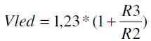
where R2 is between 1 and 5 kOhm. It is also needed to choose a proper value for LEDs current. The current is set with R115, R116 and R117 resistors, connected to pin 23 (R EXT) of LED driver. The showed value (270Ohm) sets a current of approximately 80mA per output. Because the duty cycle of each row is 1/8, the average current through the LED is 10mA. See the STP16CP05 datasheet for output current resistor set.
| R-EXT (Ω) | Output current (mA) |
| 7370 | 3 |
| 4270 | 5 |
| 2056 | 10 |
| 1006 | 20 |
| 382 | 50 |
| 251 | 80 |
| 200 | 100 |
For convenience of changing these resistors, the footprints of R115 and R116 are duplicated next to R117, named R115' and R116'.
In conclusion
Any special adjustments are required to start the device. If it is assembled properly and two microcontrollers are programmed it will immediately start running. U9 can be programmed with one of the two available connectors J4 or J4A depending on the programmer type. It is possible to need to disconnect the Vcc from U9 during programming. For that purpose JP1 is provided. The U52 must be programmed externally.
Please note, that the two double row connectors connecting the two boards are SMD type. The clearance between the pins is 2,00mm, not 2,54!
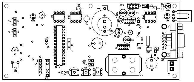
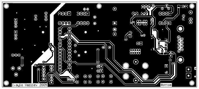
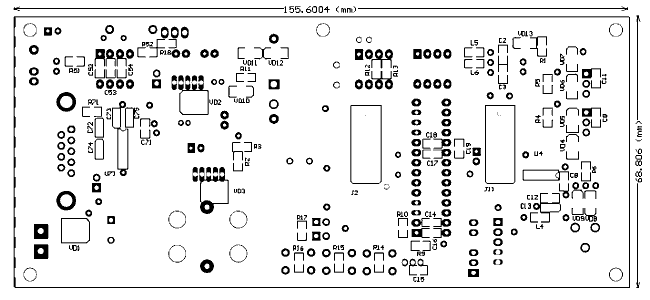
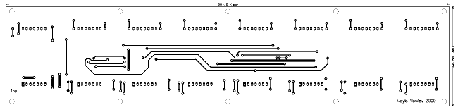
PCBs
 |
| Parts Bottom |
 |
| PCB Bottom |
 |
| Parts Top |
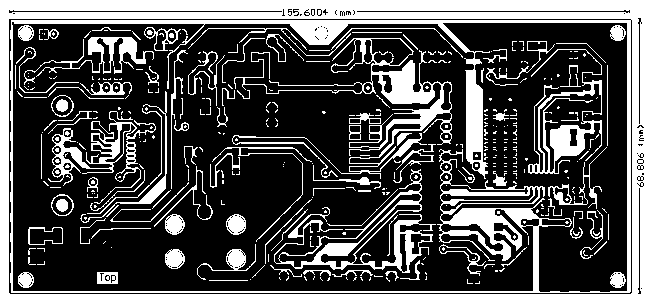 |
| PCB Top |
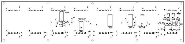 |
| Parts display Bottom |
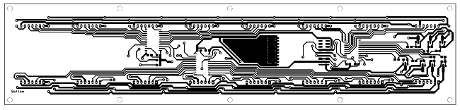 |
| PCB display Bottom |
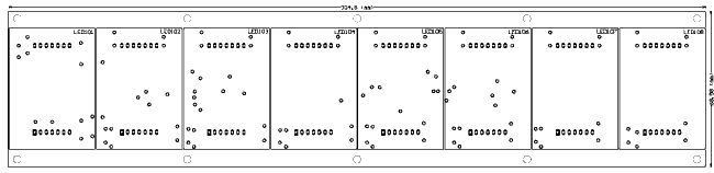 |
| Parts display Top |
 |
| PCB display TOP |
