Several years ago I wrote an article in Design Ideas called “Double µC’s PWM frequency & resolution” (Reference 1) where I mentioned how one can decrease the output ripple of a PWM-based DAC using two PWM signals having equal duty cycles with 180-degree phase (half a period delay) difference with each other.
The idea behind the PWM DAC is quite simple: it’s to filter out all of the harmonic content of the PWM signal and be left with only the DC component of it. To achieve this, the PWM signal is low-pass filtered. Obviously when you have a filter with a lower cut-off frequency the output is going to be a lot more “ripple-less,” but the transient response is going to be very slow or vice versa.
The idea that was presented in the aforementioned article was to generate an anti-phase signal to cancel out some of the harmonic components by phase cancellation action rather than relying purely on the filter itself.
This idea turned out to be useful in reducing the ripple whilst also improving the transient response. However, its usefulness is kind of limited because not all of the harmonic components of the PWM signals were cancelling each other out. To be more specific, only odd harmonics are cancelling each other and even harmonics are only affected by the filter because when we introduce half a period delay only odd harmonics experiences 180-degree phase shift and even harmonics goes through 360-degree phase shift which is same as being in phase. That results in even harmonics not cancelling each other out.
In fact, for 50% duty cycle (it contains only odd harmonics) we get ripple-free output using this technique. For any other duty cycle there is going to be some ripple, but there is still going to be some improvement in ripple amplitude compared to its single channel equivalent. We can expand this idea by using more PWM channels with different phase differences to get more ripple-less duty cycles points.
Let’s say we decided to use n channels at f Hz, if each consecutive PWM channel has 1/(f•n) delay (or 360/n phase shift) with respect to each other then every harmonic components is going to be cancelled because of evenly spaced time delays except for every nth harmonic. To be clearer, let’s say we’re using 10 kHz as our main PWM frequency and we implement four channels with 25 µs time delay (90-degree phase shift). In that case, the first channel is our base channel and it doesn’t have delay; the second channel has 25 µs delay (90-degree) with respect to the base channel; the third channel has 50 µs delay (180-degree) with respect to the base channel; and the last channel has 75 µs delay (270-degree) with respect to the base channel.
As stated earlier each consecutive channel has 25 µs (1/(f•n), f = 10 kHz, n = 4) delay with respect to its “neighboring” channel. This circuit is shown in Figure 1 along with the one-channel and two-channel versions.
 |
|
| Figure 1. | The four-channel phased-array PWM DAC circuit along with the one- and two-channel versions. |
The output of this four-channel PWM DAC is going to contain only the 4th harmonic of the base PWM frequency, and as a result the output is going to contain no ripple when the duty cycle is 25%, 50% or 75% because those PWM signals have no 4th harmonic content.
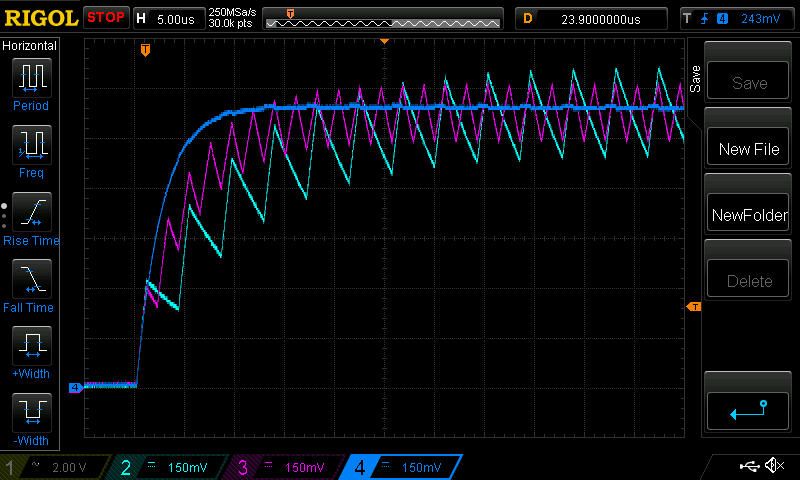
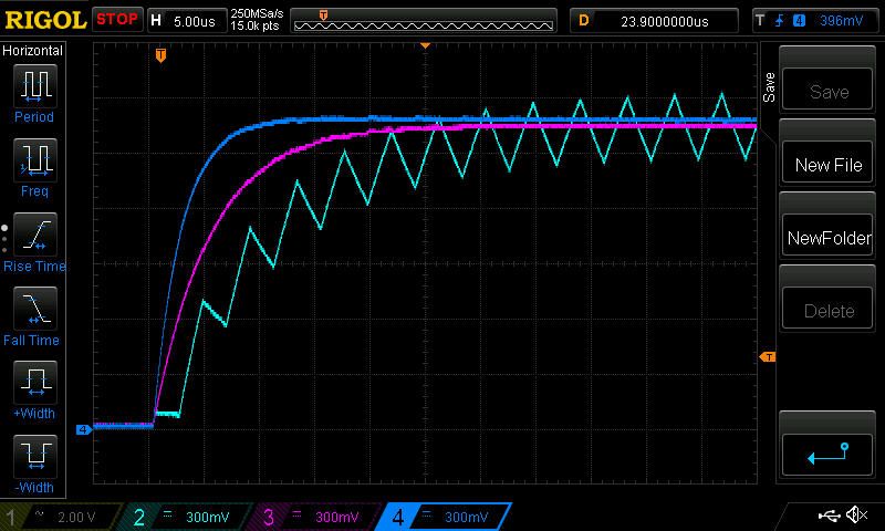
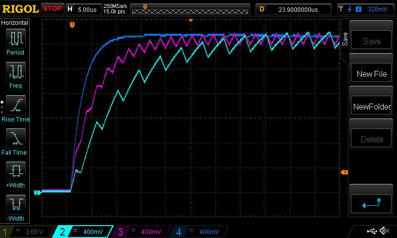
In Figures 2, 3 and 4 we can see the outputs of each circuit with duty cycles of 25%, 50% and 75%, respectively.
 |
|
| Figure 2. | The circuit with 25% duty cycle. |
 |
|
| Figure 3. | The circuit with 50% duty cycle. |
 |
|
| Figure 4. | The circuit with 75% duty cycle. |
As expected at 25% duty cycle output of the four-channel circuit (dark blue) has almost no ripple and has the fastest transient response; the two-channel circuit (pink) has ripple, but its ripple is less than the single channel’s (light blue) circuit output and it’s faster.
At 50% both the two-channel circuit (pink) and four-channel circuit (dark blue) don’t have any ripple, but the four-channel circuit has faster transient response and obviously the single channel (light blue) circuit is slowest and noisiest. And for 75% the results are the same as 25%.
For testing, the circuits are implemented in VHDL using FPGA (GitHub link is shared at the end of the post) because there were many channels and this idea can be further expanded by deploying a lot more channels. Generally speaking, if n channels are implemented, there are going to be n-1 ripple-less duty cycle points (excluding 0% and 100% which are inherently ripple-less). Theoretically, an 8-bit DAC can be implemented using 256 channels with this method, but of course that’s going to be incredibly impractical, but no one can stop you enjoying the idea. 
For the sake of completeness, this method is simulated in LTSpice up to eight channels (also in the GitHub link at the end of the post). From the same reasoning, for an eight-channel circuit you should get ripple-free output at multiples of 12.5% duty cycle points; you can see it yourself by downloading the LTSpice file. In the same way if you implement 100 channels you get ripple-less output at every multiple of 1% duty cycle.
In conclusion, by deploying more PWM channels with appropriate evenly spaced phase delays one can achieve ripple-less output at certain duty cycles and even at random duty cycles one can still improve both transient response and noise performance, which is not possible with a classical single-channel PWM DAC approach.