One of our technicians recently asked for help determining the value of an SMT inductor. It was unmarked, and was many turns of very fine wire on a ferrite core. The resistance measured 26 Ω, which for some reason gave our ancient LCR bridge a conniption, and read 30 mH along with a blinking error message. The tech rightfully felt that such a small inductor could not possibly be 30 mH.
I didn't have another bridge, but I assured the tech there are other ways to do the measurement. One way is to solder a known capacitor in parallel with the unknown inductor to form an LC tank, preferably using a capacitor with 5 percent or better tolerance and an RF-quality dielectric such as C0G (NP0). One can then measure the resulting resonant frequency and calculate the inductance from that. To measure the resonant frequency one could build an oscillator around the tank, but it's easier and faster to do the following with a standard function generator and some clip leads (see Figure 1).
 |
|
| Figure 1. |
The function generator provides a voltage step in the form of a digital logic edge, preferably a fast risetime such as obtained from the function generator's “sync” output. If a function generator is not available, a quickie oscillating edge generator can be breadboarded using any number of Schmitt inverting logic gates such as the 74xx14 as shown in Figure 2.
 |
|
| Figure 2. |
The faster the logic family risetime, the stronger the excitation of the LC tank. The actual time between edges should be long enough to allow time for the tank transient to settle, but if using an analog scope the edge frequency should be high enough to get a reasonable repetitive CRT brightness.
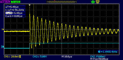
The resulting scope display looks as shown in Figure 3.
 |
|
| Figure 3. |
The blue is the logic edge trigger, the yellow is the LC tank response. The digital edge through the 10 pF capacitor twangs the tank in much the same way as a pick twangs a guitar string. The tank rings, and the resonant frequency can be measured with the cursors. It may be necessary to experiment with the value of the 10 pF coupling capacitor to get a reasonable ringing amplitude, but its value should be kept much smaller than the capacitor paralleled across the inductor.
In this case the capacitor in parallel with the inductor is 1 nF and the resulting frequency is 156 kHz. From the resonance equation
the inductor calculates to be 1 mH. This technique can be used to measure inductance down to the nanohenry region – the known parallel capacitor might need to be increased accordingly to maintain a reasonable ring frequency within the scope's bandwidth.
Measuring unmarked capacitors is a bit easier technically, but physically more difficult. Assuming unmarked surface mount capacitors, they must first be carefully removed from the original PCB with a heat gun or a dual soldering iron. Their small size and fragility requires soldering fine-gauge wires to them, but a better fixture can be made by scoring single-sided copperclad with a Dremel cutting disc to form small pads to which the unknown capacitor and short test leads can be soldered.
A voltage step is applied to the capacitor using the following setup (Figure 4) – again, the function generator can be replaced by a breadboarded logic edge generator; all we need is a voltage step with a risetime much faster than the resulting risetime of the measurement, and a period between edges long enough for the transient response to complete.
 |
|
| Figure 4. |
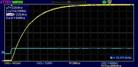
This gives the classic voltage vs. time exponential charging curve. One RC time constant is at the point where the charging capacitor voltage reaches 63 percent of the final voltage (Figure 5).
 |
|
| Figure 5. |
Adjust the scope's vertical for a display that eventually rises to eight divisions. At this scale, the 63 percent point falls conveniently near the fifth graticule division. In the above example, the cursors show that from start to 62.5 percent is 300 ns. Since the resistor is 10K, the capacitance C = t/R = 30 pF.
Now a probe correction must be applied by subtracting the known probe capacitance from the measured value to obtain the actual value of the capacitor under test. For a 15 pF probe, the unknown capacitor must be 15 pF.
The same capacitor measured with a higher quality 7.5 pF probe produced the curve in Figure 6.
 |
|
| Figure 6. |
Subtracting the probe's 7.5 pF from the measured 22.8 pF gives 15.3 pF for the unknown capacitor – close enough.
What if you don't know the probe capacitance? No problem – remove the capacitor under test and measure only the probe capacitance using the same method!
