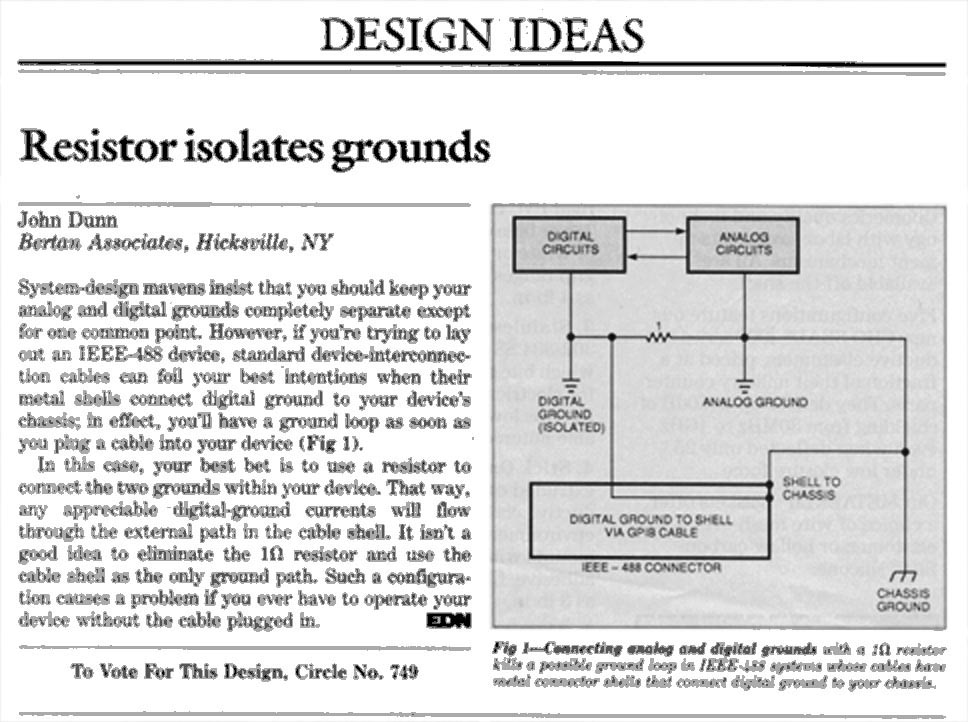
As shown in Figure 1, this issue had been previously addressed during pre-internet times in EDN of January 18,1990 but a further detailed look at the idea is warranted thirty-four years later.
 |
|
| Figure 1. | Archival design idea “Resistor isolates grounds” from 1990. |
Back then, the GPIB controller was the Bertan 200-C488. The analog product being controlled would usually be one of the Bertan 205A/210 high voltage power supplies. The 210 series high voltage supplies delivered in the neighborhood of 200 W, not the highest power level one might encounter, but still high enough to make some heat.
The controller and the controlled when standing alone and apart would look something like Figure 2.
 |
|
| Figure 2. | Block diagram of the Bertan 200-C488 GPIB controller and the controlled Bertan 205A/210 high voltage power supply. |
The controlled item had an analog ground against which a controlling analog voltage would be applied and against which voltage and current monitoring signals would be obtained. The controlled item also had some rudimentary on/off signals. The controller had inputs and outputs to match.
During product development, the first attempted interface between the two didn’t work too well (See Figure 3).
 |
|
| Figure 3. | Controller and controlled with a ground loop current whose current magnitude interfered with both control and monitoring. |
The cabling between the controller and the controlled was found to be carrying a current loop whose current magnitude really messed up both control and monitoring. Just a few millivolts arising from heaven only knows what can send a lot of current through a loop of just a few milliohms.
This was a trap that had been inadvertently fallen into during design. (Mea culpa, there.) The prospect of a major redesign with elaborate isolation provisions was appalling so we stepped back a little to look things over and find a simpler remedy.
With the controller still in development, it was realized that its digital and analog grounds needed to be tied together, but that adding a 1 Ω resistance between the two as in Figure 4 would have no disruptive effect.
 |
|
| Figure 4. | Modified controller and controlled with the digital and analog grounds of the controller tied together with a 1 Ω resistance between the two. |
With that resistor in place, the ground loop situation was very much improved (Figure 5) meaning that the current flow in the ground loop was very much reduced to below inducing any disruptive effects. The current itself didn’t go to zero, but it went down to a much lower and non-disruptive level.
 |
|
| Figure 5. | Controller and controlled with a diminished ground loop current. |
The hard wired connection between the digital and analog grounds located at the controlled item was of no concern to the controller, but with the magnitude of the ground loop current flow lowered way, way down, that current no longer perceptibly affected anything.
Additionally, If the controller were to be disconnected, the controller was still stable with its revised grounding arrangement. There was no loss of operating stability whether it was connected to the other equipment or not.
