Zoran Mijanovic & Nedjeljko Lekic
EDN
This Design Idea shows how a single microcontroller port can drive a lot of output lines through shift register. In this case we use the shift register with strobe control to achieve perfect output line control.
Shift register outputs can drive LEDs, relays, etc. In other words, they can be used as (additional) general purpose outputs.
Today there are shift registers that have DATA and CLOCK inputs only, like 74HC164, and shift registers with same inputs plus STROBE control input, like 74HC4094 or 74HC595. The shift registers without STROBE control have short-term transient states at outputs during shifting. Transients occur because shift register is directly connected to output lines. This kind of shift register can be used for driving LEDs and similar devices where short-term transient is irrelevant. For example, the human eye can't notice LED flickers shorter than 10 msec. The shift registers with STROBE control have two registers.
 |
|
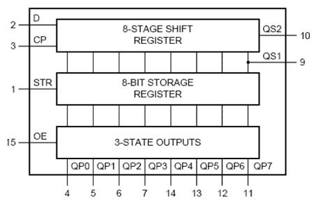
| Figure 1. | This is a logic diagram of the shift register with strobe input (74HC4094). |
The first one is shift register and the second one is storage register. The storage register keeps its data frozen while the new data are being loaded in shift register. After the new data is shifted in, STROBE pulse is used to transfer all data bits to storage register at once. In this way outputs are set without transients. This is a new quality which makes this shift register applicable for driving transient sensitive devices like TRIACs, super bright LEDs, etc.
There are several different solutions for driving shift register with few I/O lines. Some of the Design Ideas referenced below describe driving shift register without strobe control.
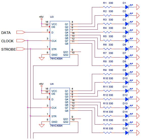
In order to explain how to drive shift register with STROBE control over only one I/O line we show circuits from figures 2 to 4. Figure 2 shows shift register controlled with three lines: DATA, CLOCK, and STROBE.
 |
|
| Figure 2. | The shift registers shown are controlled with three lines: DATA, CLOCK, and STROBE. |
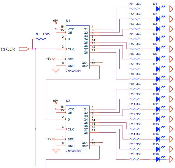
If STROBE control input is connected to 5V, logical 1, we practically get shift register without STROBE control. For such a case we can apply the solution from Article "Drive 16 LEDs with one I/O line", where one I/O line drives DATA and CLOCK input (Figure 3).
 |
|
| Figure 3. | One microcontroller port controls DATA and CLOCK inputs of shift registers. The STROBE input is inactive, connected to 5V (logical 1). |
But when we want to use STROBE signal to get transient free output signals, it seems that we need two ports, CLOCK and STROBE. Further improvement is possible by adding a monostable multivibrator circuit.
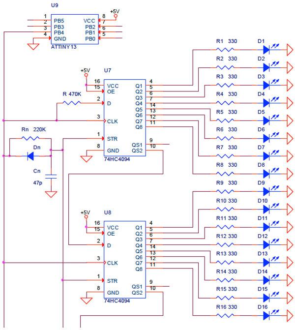
Finally, we propose the simplest solution. In this solution STROBE input is controlled over RCD network (Figure 4).
 |
|
| Figure 4. | The shift register (with STROBE input) is controlled over one I/O line, using RCD network. |
The RCD network is formed from discrete resistor Rn=220KΩ, capacitor Cn=47p, and diode Dn. The RCD network enables that STROBE signal rapidly drops to zero, but slowly rise to one with time constant Rn×Cn=10.34 µsec.