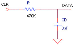
Let us look at the first shift register. The microcontroller drives CLOCK input directly. The same signal passes through the RC filter and drives DATA input D (Figure 5). The RC filter is formed from discrete resistor R=470KΩ and D input pin capacitances, producing a time delay of approximately
td = R × C × ln2 = 470KΩ × 3 pF × 0.7 ≈ 1 μsec.
 |
|
| Figure 5. | The delay circuit schematic representation is shown here. |
To write “zero” in the shift register, the microcontroller holds low level longer then td i.e. 2.5 μsec and after that sets high level.
To write “one,” the microcontroller holds high level longer than td. After that microcontroller generates a short negative pulse (100 nsec).
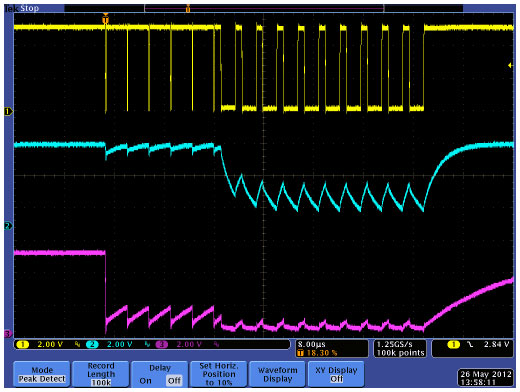
The oscillogram in Figure 6 illustrates it. Channel 1 shows CLOCK signal, channel 2 shows DATA signal, and channel 3 shows STROBE signal. We used Tektronix oscilloscope DPO4034 with high-voltage probes TPP0850. These probes have 40MΩ input resistance and only 1.5 pF input capacitance. Using these probes we can be sure that DATA and STROBE signals are captured well, without significant capacitance load distortion.
 |
|
| Figure 6. | This oscillogram was captured while writing bits sequence 1111100000000000 in a 16-LED dot-bar/bar-graph display. The upper (yellow) trace is CLOCK, the middle (blue) trace is DATA, and the lowest (pink) trace is STROBE. |
The shift registers are clocked by rising edge of CLOCK signal. This corresponds to local minimum of the DATA signal. From the oscillograms, it can be seen that DATA minimum for logical zero is 1.2V and for logical one it is 4.2V. The shift register logical threshold is 2.5V, so we can conclude that these voltages 1.2 and 4.2V guarantee sufficient voltage margins. In the circuit realization, 16 bits are stored in shift registers in approximately 50 µsec.
Figure 6 also shows how the STROBE signal (pink) rises after all 16 bits are loaded. In contrast to shift register without STROBE,1 in this case (with STOBE control) port should not stay too long on high voltage level, to prevent unwanted STROBE activation. For this case high level time should not last more than 6 µsec.
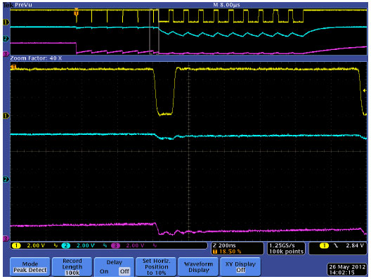
In Figure 7 we used zoom function to show negative CLOCK pulse that writes logical one. In our realization the microcontroller Atmel ATTINY13 generates this pulse as short as 100 nsec.
 |
|
| Figure 7. | The narrow CLOCK pulse that writes a logical 1 is seen here. |
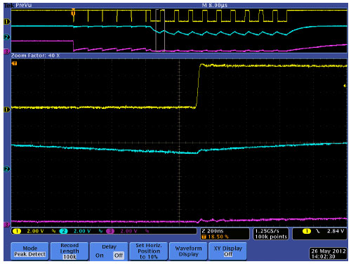
The oscillogram from Figure 8 shows the CLOCK pulse that writes logical 0.
 |
|
| Figure 8. | This is the CLOCK pulse that writes logical 0. |
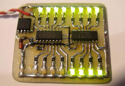
Figure 9 shows the photo of 16-LED dot-bar/bar-graph display with 74HC4094 shift registers. There are two 8-Bit Serial-Input/Parallel-Output shift registers. We made it with one-side PCB, so all tracks are visible in this photo.
 |
|
| Figure 9. | The 16-LED dot-bar/bar-graph display uses a two 8-Bit 74HC4094 shift registers. |
The software is extremely simple (Listing 1). It turns the LEDs on one by one, every 500 sec until all LEDs are on. After that, it turns all LEDs off and starts the cycle again. Below are two short videos showing the LED function and oscilloscope screen with DATA, CLOCK, and STROBE signals.
Demonstration Video
Oscilloscope screen video with DATA, CLOCK, and STROBE signals.
References
- Drive 16 LEDs with one I/O line
- Introduction to 74HC595 shift register - Controlling 16 LEDs
- Edited by Charles H Small and Fran Granville, “Microcontroller provides low-cost analog-to-digital conversion, drives seven-segment displays,” EDN, May 10, 2007.
- Raynus, Abel, “Squeeze extra outputs from a pin-limited microcontroller,” EDN, August 4, 2005.
- Rex Niven, “RC lowpass filter expands microcomputer’s output port,” EDN, June 21, 2007.