This tutorial shows you how to control 16 LEDs with just 3 control lines. We do this by daisy chaining 74HC595 shift registers
The 74HC595 shift register has an 8 bit storage register and an 8 bit shift register. Data is written to the shift register serially, then latched onto the storage register. The storage register then controls 8 output lines. The figure below shows the 74HC595 pinout.
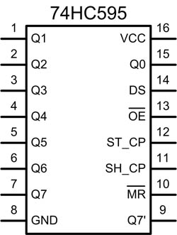
Pin 14 (DS) is the Data pin. On some datasheets it is referred to as "SER".
When pin 11 (SH_CP or SRCLK on some datasheets) goes from Low to High the value of DS is stored into the shift register and the existing values of the register are shifted to make room for the new bit.
Pin 12 (ST_CP or RCLK on some datasheets) is held low whilst data is being written to the shift register. When it goes High the values of the shift register are latched to the storage register which are then outputted to pins Q0-Q7.
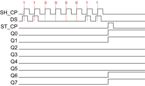
The timing diagram below demonstrates how you would set the Q0-Q7 output pins to 11000011, assuming starting values of 00000000.
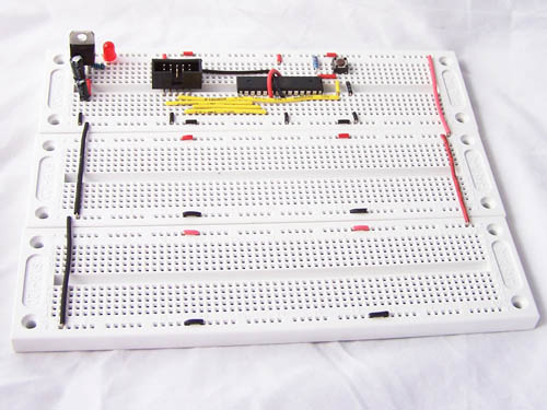
The circuit we are building is showed below, followed by the build steps
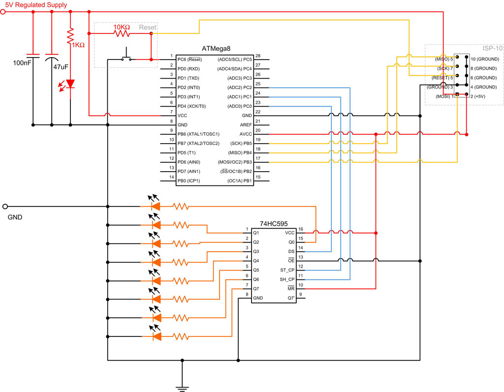
We will start with an Atmega8 breadboard circuit which we have used for many of our other tutorials. We add 2 extra breadboards and route power to these.
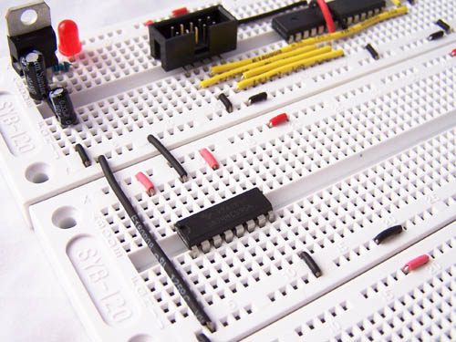
We add the Shift Register and connect it to +5V and Ground.
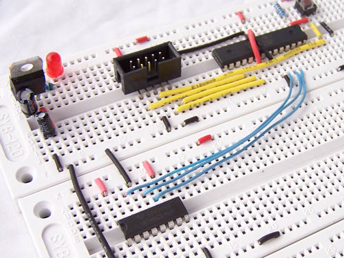
We now run the following control lines between the microcontroller and Shift Register
- PC0 to DS
- PC1 to ST_CP
- Pc2 to SH_CP
These are the blue wires shown below.
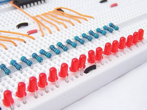
Next we connect up the LEDs and resistors. I used 510 Ohm resistors, but a range of other sizes are acceptable. ohmslawcalculator.com has a great LED Resistor Calculator that you can use.
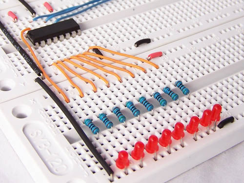
To demonstrate the circuit, I wrote a small bit of code which produces a knight rider pattern on the 8 LEDs.
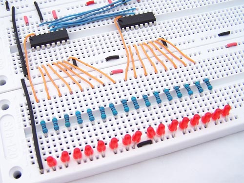
This is all very impressive, but didn’t I say we were controlling 16 LEDs? To do this we need to add another 74HC595 shift register, more LEDs, more resistors and more orange and blue wires.
We use the Q7’ pin to daisy chain the shift registers together.
The modified circuit is shown below.

To code to produce the 16 LED knight rider pattern is
Code:
We just stopped at 16 LEDs, but we can continue daisy chaining more shift registers. This technique is not just limited to LEDs of course and we can use it to multiply output ports to drive many other kinds of devices.
One word of warning regarding this technique. When you power on the circuit, the output lines are set to some arbitrary value. Now it takes less than a microsecond to set them to your desired values, but for some circuits this may cause problems. In that case you can use to MR and OE pins to reset the storage registers.