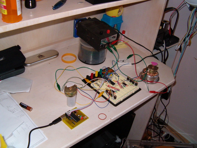
Since I finished my degree in April, I have been looking for work. The search has been slow but hopefully soon I will be making the big bucks. To fill my spare time I decided to do something with the mounds of electronics and such sitting in my room. First is to build a robot using stepper motors.
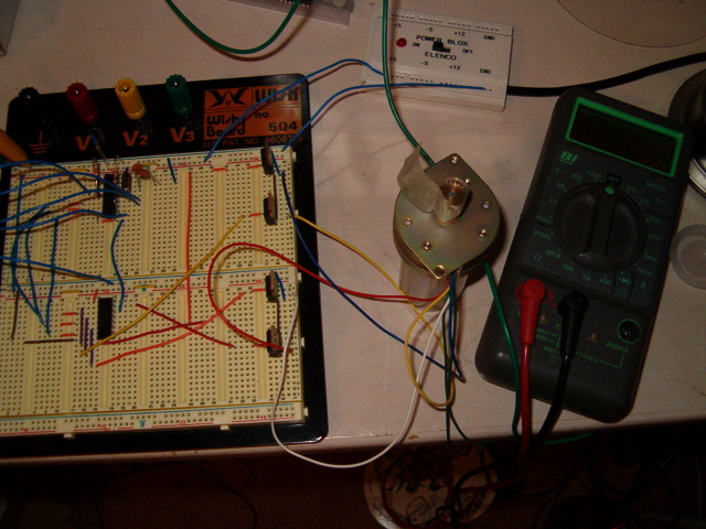
The stepper motors were purchased at a local auction house. They took apart old hard drives and printers and such selling the parts separately. You can usually barter and get a good deal, the ones being used in this circuit cost about $3 each. These particular motors are unipolar steppers. You can usually tell by the number of wires coming out. This one has 6 wires coming out of it: 2 green, 1 blue, 1 yellow, 1 red, and 1 white. In a 4 phase unipolar motor There are 2 coils which are center tapped and have a wire for each of phases. If the wire colours are random or if there were only 5 wires, then you would have to use an ohmmeter to distinguish between the phases and center tap. Fortunately for me 2 of the wires were the same colour, so they must be the center taps. Another plus was the wires were grouped in threes.
There is a lot of online literature about stepper motors and controlling them. A Google search turned up the circuit below. It uses a PIC microcontroller to sequence the steps, TIP120 Darlington pairs for the switching circuitry, and a 4050 hex buffer for logic levels and circuit protection.

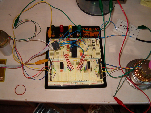
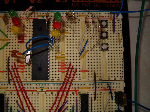
For the first circuit I used a PIC 16F628A to test the stepper motor and find out how fast I could get it going. Just a note to people who have built or want to build the LVP, I had problems with trying to get the internal oscillator working. It might be a quirk with how this paricular chip works or a problem with how the configuration bits are being set with the programming software. But for the test circuit I used a 4 MHz crystal. A stepper motor works by pulsing each phase in a certain sequence. The delay between pauses determines how fast the shaft rotates. Beginning at a 50 ms delay I was able to get it down to 3 ms for this particular motor.
Doing some some quick calculations:
On the motor it states that each step is 7.5 degrees per step, so that makes 48 steps for one full revolution.
4 phases/step x 3 ms/phase x 48 steps/revolution = 576 ms/revolution
Converting to revolutions/second we get roughly 1.736
1.736 revolutions/second x 60 seconds/minute = 104.16 RPM, not a bad speed.
The motors are rated for 24 V, But I am running them at 13V because that is all I had available.
Source code
Compiled hex file


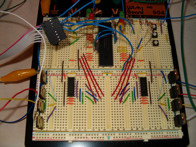
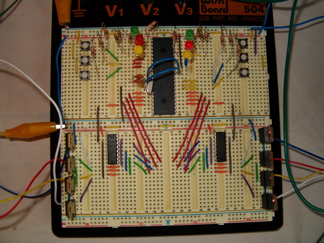
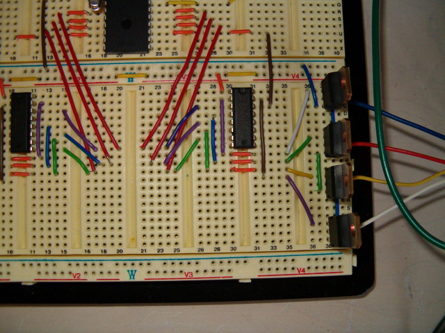
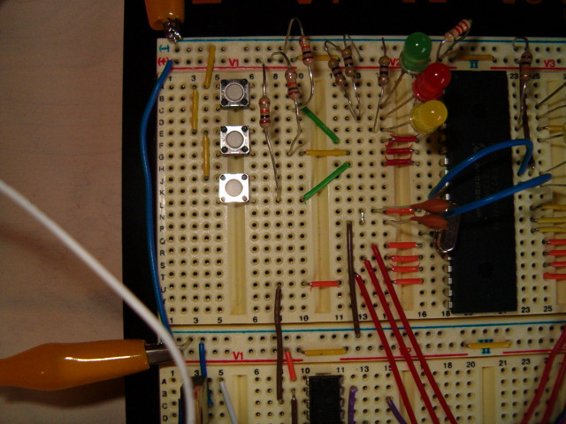
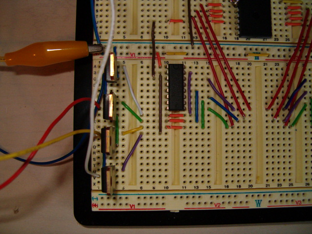
This second circuit is made with a 16F877A PIC micro. It runs 2 steppers with controls for direction and stopping. The 877A has more I/O pins than the 628A. I can add another motor, buttons and LEDS without having to worry about running out of pins. Be sure to set the ADCON1 register for any PIC that has ADC, it is good practice and usually saves you from lots of headaches. If you notice in the video the stop button for the motors does not toggle the motor on and off. I had some debouncing issues with the inputs so for now I just stopped the motor when the button is pushed and the motor will continue in the direction it was going in before when the button is released.
The motors are set up to be independantly controlled. Both motors are being run off the same supply of 13 V. I haven't checked the current draw yet, but since there is no smoke yet I'm sure it should be fine. As a final note it is always easier to change the software/firmware than the hardware. If you have build this circuit and notice that your stepper motor is not stepping correctly, just go into the code and change the stepping sequence instead of pulling wires. Most often when you start messing with the circuit you forget where certain things go.
Source code
Compiled hex file