Bernard shows us how to use an use an accelerometer as a mouse. This project uses a MEMS X/Y accelerometer, a PIC microcontroller and a old mouse. He also describes a trick for powering the new mouse with the unused RS232 serial control lines.
This article was submitted by Bernard Klinc as part of the “Hobby parts for articles” program. Bernard did not need the Arduino kit so we sent him an 2 × 16 LCD display for this great article.
This project demonstrates the use of a accelerometer as a computer mouse, but first what is an accelerometer? Its a device that can measure acceleration and the pull of gravity. There are multiple ways of doing this, the particular one I’m using works with the capacitive method. Inside the chip is a capacitor with an extra plate in the middle that can move. As you know the closer the objects are together the bigger the capacitance, the circuit inside the chip measures the capacitance difference between the two plates and the middle one. Finally the circuit coverts this in to a analog signal between 0V and 3.3 V. All of this is small enough to fit in to a small SMD chip.
The accelerometer used in this project is MMA6270 manufactured by Freescale Semiconductor. It has two sensors inside the chip, each facing at 90 ° to each other providing the X and Y axis. This is perfect for a mouse. In this case we are using it to detect the angle of the mouse. When the mouse is completely horizontal bough X and Y have 0G applied to them, but when we tilt the mouse the gravitational pull starts to cause force on the axis. But we wanted to move the mouse cursor using this. So we put on a PIC microcontroller, connect all the outputs to the ADCs and send the data over to the PC.
To mount this part I soldered short leads to each of the necessary pints. These short wires then could be soldered into my final project or an adaptor as seen on the breadboard below.
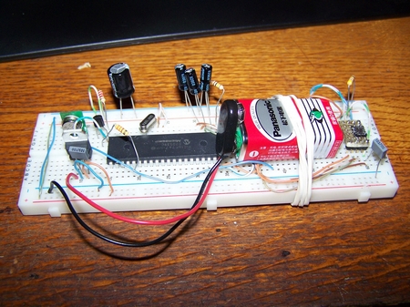
Testing started on the breadboard, It has proven to work pretty good. Later on I tried to make it wireless but the 433 MHz modules I had were not fast or reliable enough. It did work, but not very good, so I decided to go back to a cable. I used a Visual Basic program on the PC as the driver for the mouse because I was too lazy to make it compatible with a standard COM port mouse. Making it work as a normal mouse could be done easily.
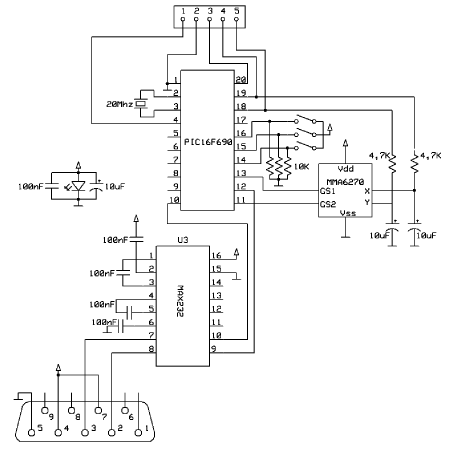
The next problem is power, How to power the circuit since the com port doesn’t have a power supply line. The solution are the flow control lines on the COM port. Several control outputs are available as they are used by old COM port mice and keyboards. Windows puts these lines to high during the boot up, if the mouse doesn’t properly respond in a few seconds it puts those lines back to low. About 10 mA of current can be pulled from these pins. But still it’s not solved yet the voltages on the com port are around 8 V to 13 V and are current limited. My solution was to tie several of the unused control lines directly to a blue LED witch clips it to about 3,4 V. This is perfect since we need 3.3 V for our accelerometer and the PIC has no problem running on 3.3 V. I had doubts in the MAX232 but it turned out to work fine.
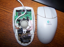
With the PIC and a small program we can sense the angle using the accelerometer to detect gravity and send the measurements to the PC. I used an old mouse and wired directly to the mouse button to get the click signal. I had to cut the traces on these buttons as the original mouse chip was interfering.
Here is my finished accelerometer based mouse! Check out the video of it in operation below.
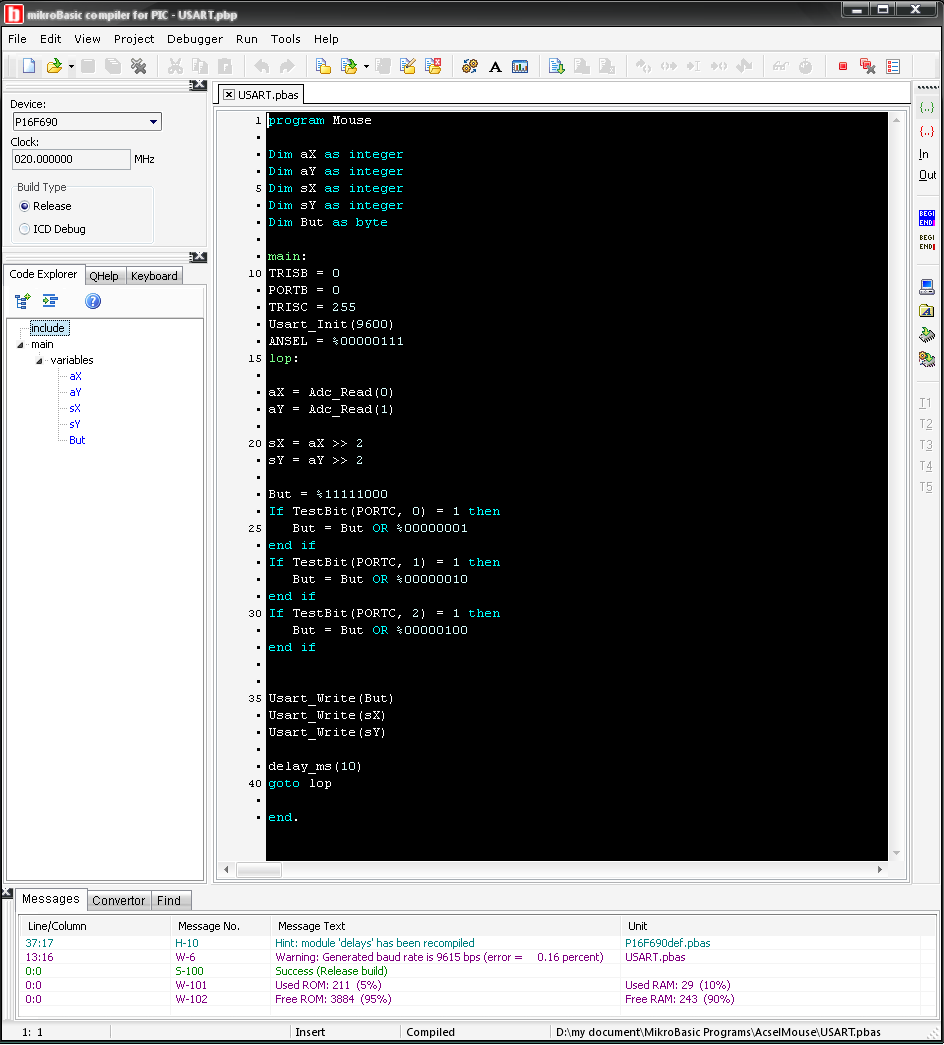
Software Source Code: