I bet nobody has given you a business card before that actually dials you up by itself! Read on to find out how I did it ....
Do you like making things? Do you do it for money, or would like to? If so, you need a business card. These can be your best advertising, but we all know business cards are boring and get thrown away. I have toyed with plastic or etched stainless cards before - these are really cool, but cost a lot, and are not really distinctively "you".
Do you make goods out of leather? Then make a leather business card. Do you make handmade greeting cards? Then make your business card look like one of these! Even better, make one that is actually useful for whoever you're giving it to, so it CAN'T be thrown away. I'm into making electronics, so what better way to advertise my skills than an electronic business card. Here are two experimental "extreme" business cards that are almost impossible for someone to throw away - one in the form of a key ring torch and one card that actually dials me up by itself! This one has a computer inside with more processing power than took the first astronauts to the moon (No, I'm not kidding!), yet the main part costs less than 50 cents. I'm also working on one that plugs into a USB port on a computer so that people can email me directly from a link, or look at a portfolio of my work.
Even if these ideas don't grab you, maybe they'll fire your imagination to think how you could make a truly unique card that uses your skills and tells people how creative you are.
I won't kid you - these two cards need some serious construction skills, and are both experimental (particularly the dialler), so are no beginners projects, but wait 'til you see the face of the first person you give one of these to! Don't try these designs unless you have successfully made a few electronic items before - they need good soldering skills, and ideally a way of making some printed circuit boards, although if you soldering skills are REALLY good, and you are making just a few, it is possible to make versions of both of these cards without circuit boards, and just "point to point" wiring - my prototypes were done like this.
Firstly the torch. This is the easier of the two. Although you could use some PVC cards to enclose a hand-wired version (keep reading on to see this technique used in the "dialler"), making copies is much easier with a proper PCB. A tutorial on how to make a PCB is beyond the scope of this article, but if you haven't tried it before, it is a really good technique to be able to do and opens up a countless variety of electronic projects. Here is an instructable on a simple toner transfer PCB - personally I find more repeatable and professional results with the photographic method - couldn't find an instructable for this one, but there is plenty of info on the web - I use a very cheap 500W halogen light from the local hardware store to expose mine for a few minutes, and then develop, etch and tin. If there is enough demand, I might get some universal "torch" and "dialler" boards commercially made.
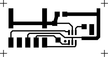
Anyway, assuming you can get a PCB made up, the file which I used is included below - this can be modified on a standard graphics package. If you can't read EPS files, then try the 300dpi bitmapped version included below as well. You can of course use a specialised PCB package, but I wanted an unusual cursive font on mine, so just hand-drew the design on a graphics package. This allowed me to incorporate my name into the actual circuit board - the electric current actually goes though my name! If you want to produce a reasonable batch, you will probably want to tile your image over the page after you have made your changes.
Here you can see the parts - a PCB, coin cell (CR2032), a coin cell holder, a 3 mm LED (any colour should be fine), a PCB-mount switch, and a resistor. A complete parts list for both projects is available as a link below if you want to find where to source some of these components. The value of the resistor is usually around 68 ohm for most colour LEDs. It is a surface mount device, so is very small - the exact type you get isn't critical - I used a "1206" package as it is easier to solder, but 0805 or 0603 packages can be soldered on as well if you have good eyesight! If you are using a blue or white LED, they are meant to be too high-voltage to really use with a single coin cell, but if you use a bright one, you can just remove the resistor completely (short with a blob of solder or use a "0 ohm resistor") and the light, although not full intensity, should be quite bright (see the image of it turned on a couple of pages later). You want to get the highest intensity 3mm LED you can find - there are some great deals on ebay, which is usually the cheapest place to find these.
If you want more information on how both of these projects work technically, including how to properly choose resistor values, see the extra technical information sheet that I have posted below as well. I could make up a batch of 100 of these for under $1 each, including PCB -not bad for some extreme marketing, but you could probably even half this price if you were serious about making these in quantity and could do without the battery holder (see the notes in the parts list about welding batteries).
Insert the battery with the positive side up, and press the button, and you should have a functioning key ring light! As I mentioned, this design is an experimental prototype only - if I produced these on mass, I would probably change a few things. Firstly, I would make the board smaller still (for cost), and put the name/contact details on the reverse of the board. I might also change the CR2032 cell to a CR2016 as this is thinner, and cut a hole in the board to mount it inline. This would make the whole thing very thin indeed. I might even encapsulate the board in clear heat shrink tubing or the like, to stop it shorting out on keys whilst in the pocket.
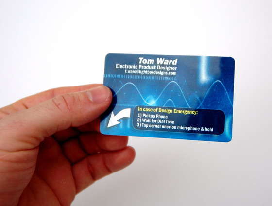
I'm not going to try to convince you that this is a particularly useful invention. It is an unashamed novelty - one that is designed as a show-off piece for giving to my better leads. The idea is that it actually dials me up by sending the series of audio tones (Called "DTMF") that the phone system uses to dial numbers. You pick up a phone, hold the corner of the card to the mouthpiece, and tap it, and the card emits these tones, and dials my number. Think of a musical greeting card on steroids - you can program it to dial any number, and it could easily be modified to play a tune or even speak a message given a little hardware modification and some more memory. I could make a batch of these for around $2.00 each - a similar price to some of those flash etched stainless steel cards, but a lot more inventive! The proto was a little more expensive, due mainly to the price of some solderable lithium cells (more about this later). Like the torch business card, it is not meant to be given out in the hundreds - I have a standard "boring" business card for those who just need my contact details and others for those I am really trying to impress!
This is all possible because of miniature programmable microcontrollers - they are now so small and so cheap, they can be put into disposable items. The one I use is made by "Microchip", and costs 39 cents in quantity (and not much more in singles). It can run any small program that you write, and can run it at 4 million instructions per second. I can safely claim (for the moment), that I have the world's most sophisticated business card! You could easily program the microcontroller to do any number of things that fit within the program memory instead - perhaps a simple version of the "business card torch" described earlier that has a flashing light or even "S.O.S." function. Your imagination is the limit here.
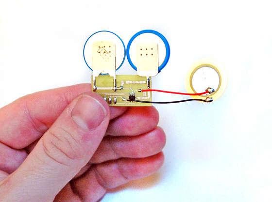
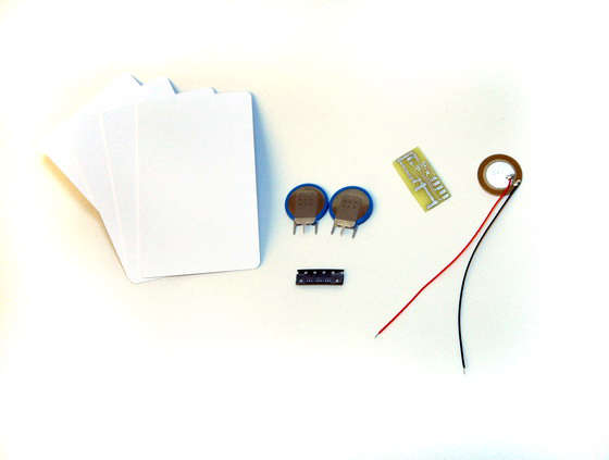
Here you can see the main parts. As before, a detailed parts list for both projects can be seen below if you are mad enough to actually want to build it. The items on the left are blank PVC ID cards - available very cheaply. These can be used to enclose all sorts of other electronic gadgets (more about that later). The batteries are in the middle - I used two PCB-mount CR2016 batteries, as these are very thin (1/32" or 1.6mm). The PCB is next to these (see below for an EPS file, and a 300dpi bitmapped version if you can't read an EPS), and on the right is a piezo disk which is used to create the tones, and also as a "switch" to detect the tapping. On the bottom is one of the microcontrollers (actually, shown here is a strip that contained five of them) - it is a PIC10F200.
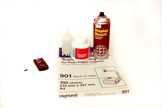
If you click on the second picture, you can see some miscellaneous equipment that you will need - some printable OHP transparencies, some spray glue, some PVC solvent cement (used for joining PVC pipes), a device for programming the chip, and on the far left, 5 pins cut off a strip of 0.1" pin headers, to connect the programmer to the board. The PIC programmer itself is ridiculously cheap for what it is ($35.00), and can be used for countless other projects as well - Many thanks to Microchip for making such a great development tool available at such a cheap price. The bottle next to the PVC cement is just to make application of the glue easier - if you do use your own bottle, make sure it isn't made out of a plastic that is dissolved by the cement!

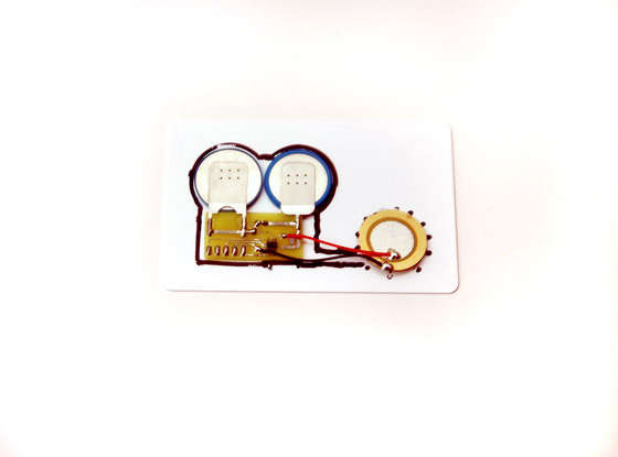
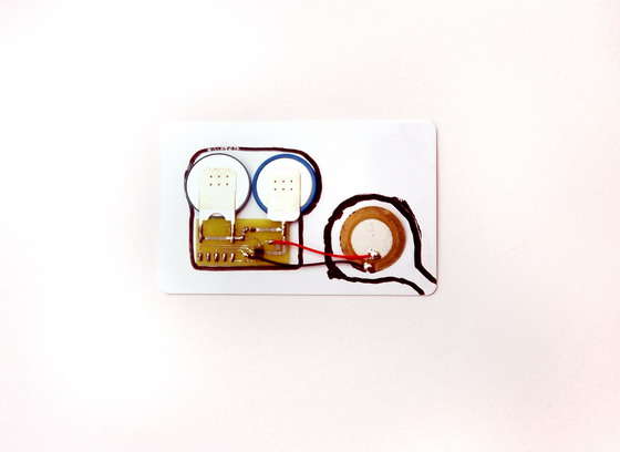
Assembling the electronic components is not hard, but needs a steady hand, and some experience with soldering. Solder the components as per the image. The two batteries straddle the PCB and are opposite ways around - the one on the left should have its positive side up. You can't see from this image, but you also need to solder a piece of wire between the two battery contacts on the opposite side of the board as well. The PIC is soldered to the PCB on the supplied pads - pin 1 is on the bottom left - if you have very good eyesight, the writing should be the correct way up when you are soldering this item as shown in the image. I find the technique of tacking one pad down with solder first to hold it, and then soldering the other pads, works well. The piezo is soldered to the two pads closest to the chip. I have reduced the length of the wires so that the whole assembly fits within the space of a single blank PVC card.
The next step is to put the dialling program into the chip. If you have bought the PIC Kit 2 programmer, it has everything you need with it, but you should download the latest version of the programming software from here, as some versions of the software don't support the PIC10F chips. Download the code as well from the bottom of this page, unzip it and put it in a directory somewhere on your computer - then from within MPLAB, go to the "Project" menu, select "Open", and navigate to the "BCard" file. Change the stored number (around line 90 in the code) to your phone number rather than mine(!) - it can be a longer number, but after the last digit of your number, the following line should read:
retlw h'ff'
Go to the "Project" menu again, and select "Build All" - check there are no errors, and you are then ready to program. I use a simple technique of inserting a broken-off strip of 5 pins from a strip of 0.1" header pins into the programmer, and then just touching the 5 pins (see the picture) whilst programming. This is a little fiddly, but as the erase or program cycle only takes a second or so, it is quite manageable. If you are experimenting, it is well worth soldering the strip of 5 pins onto the board until you have finished your changes. When you are ready to program, select the "Erase" and then "Program" options from the "Programmer" menu. If all works OK, you should be able to remove the programmer, and tap the piezo to hear your phone number being dialled!
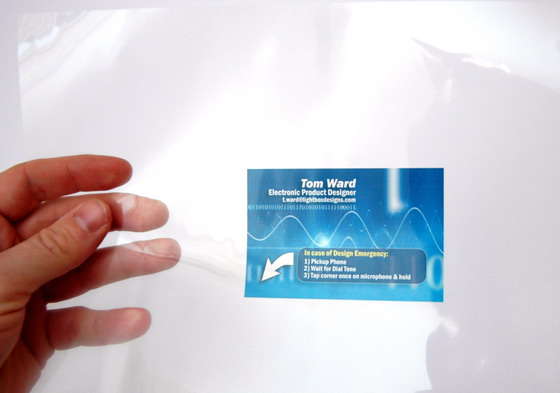
Time to make it pretty! First use a graphics package to design your business card. I used a background image to make mine look a little different, and then had the writing in white. The design should be 1/8" larger on all edges (3mm) to allow for a "bleed". Reverse the image in your graphics package if possible (or otherwise at print time within your printer driver), and then print onto a transparency. Turn the transparency back over the right way, and you will have a nice design protected by the thickness of the transparency plastic. To see more detail of this technique, check out my "Professional Looking Gadgets" instructable - you may even notice a similarity in background images!
Note that I made a conscious decision to omit my phone number from the card to force someone to try it out. It may be a wiser decision to list the number on the card as well in case of problems getting it to work!

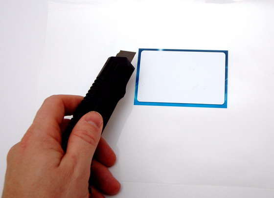
Turn the transparency back so that the ink is up (should be reversed writing), spray on a light covering of glue, and stick on one of the blank ID cards. Then trim neatly around the image with a sharp knife or scalpel. Click on the second image to see what it looks like so far!
This step shows you how to make enclosures for electronic gadgets using PVC cards - using solvent cement to glue them together - this could be a separate instructable just by itself. I have now used this technique for other things like a credit card torch, which was wired using stick-on copper tape (perfect project for kids), and even a bugging device. They look professional, even without a graphic overlay, are easy to build, and super cheap as well. You can make them any thickness using multiple spacer cards between the front and back. For this project we need two spacer cards as they are around 1/32" (0.8mm) each. For thicker projects you can cut strips of "PVC foam" and use this as a spacer instead.
Place the circuit board on the card, and draw around with an OHP marker or similar. Then cut out the inside with a pair of small, sharp scissors. Doesn't really matter if you make a cut in from the side, as this will be hidden anyway, but if you are a little retentive like me, you can drill a hole in the middle first, and then cut out the inside without making a cut to the edge. The dotted line shows where you need to cut slightly inside the line to form a lip where you can glue the piezo disk.
The second spacer is almost identical, but doesn't have a cut-out for the wires, and the cut-out for the piezo disk is oversized, with a channel to the corner - this is where the sound comes out!
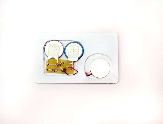
Turn the card that you have stuck the overlay onto upside down, with the arrow pointing to the bottom right, then stick on the first spacer card with the PVC cement. Put the circuit board in the hole now (use a dab of glue if you wish), and then glue (neatly!) the edge of the piezo disk onto the circular lip. I used some more PVC cement, but would probably be best to use superglue or Epoxy - this item should be held tightly. Then glue the second spacer over the top of the first with some more cement (yours should now look like the picture), and finally glue a blank PVC card to the back.
The overall card thickness is governed by the batteries (1/16" or 1.6mm) - I have added another two PVC cards to the front and back, but you could make these even thinner so that the whole card is approaching this thickness of just the batteries.

Time to test out! Pick up a phone, wait for the dial tone, and put the corner of the card on the microphone. Tap it once and your number should be dialled.
I did warn you that this took a little skill to make, and that it was very experimental - I get only around a 50% success rate maximum at the moment when dialling, and getting the number recognised accurately is highly dependent on a number of factors including your exchange and the mounting of the piezo disk, including the shape of the cavity cut inside the card. I am now working on making some improvements to the design to make the recognition close to 100% - for those who are very technically minded, I am redesigning the card to drive the piezo with a pseudo sine wave rather than a square wave using filtered PWM signals, and am going to increase the tone and space times as well. If you are a bit of a techno-nerd like me, then check out the technical notes below to look at how this whole thing works. In short, unless you are a glutton for punishment, wait for my updated postings with these changes before beginning construction!
In case you were wondering, this doesn't work from a mobile phone, as you need a dial tone from the exchange for it to recognise the DTMF tones generated, but as I mentioned, this is more of a novelty marketing exercise than a universal way to dial a number. Time for you to now enjoy having the world's most technically advanced business card!