EDN
Texas Instruments' UCC3895 offers a good base for building a high-efficiency, pulse-width-modulated, switched-mode power supply that suits either current- or voltage-mode control. Designed for driving a full-bridge power inverter using two sets of complementary outputs, OUTA through OUTD, the circuit controls power by phase-shifting outputs C and D with respect to A and B. The manufacturer's data sheet provides a detailed description. However, when lightly loaded and configured for current-mode control, the controller can produce asymmetric-width pulses on its lagging outputs, C and D, under start-up conditions. Reference 1 provides a complete description of the problem and a workaround.
 |
||
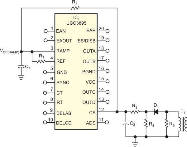
| Figure 1. | An added resistor, R1, helps improve light-load operation of a popular switched-mode power-supply controller by eliminating output asymmetry. |
|
Unfortunately, the workaround evokes other problems when you use the IC in other circuit implementations. Figure 1, from Reference 1, shows a partial schematic featuring the UCC3895 in a peak-current-mode-control circuit in which R1 serves as a pullup resistor, providing a dc offset for the voltage ramp. However, for a significant portion of the ramp waveform, diode D1 doesn't conduct and therefore narrows the power supply's dynamic range by cutting off a portion of the ramp voltage at IC1 's Pin 3.
 |
||
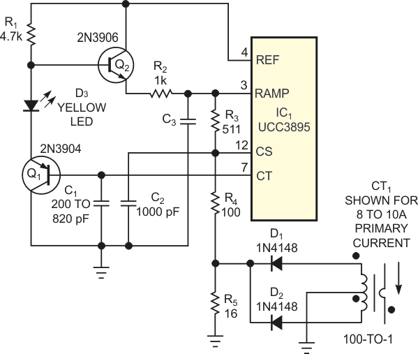
| Figure 2. | For even better performance, add a level-shifting amplifier to the ramp-voltage path. | |
Figure 2 shows another approach that requires additional components but delivers the full magnitude of the voltage ramp to Pin 3 of IC1 and provides the approximately 1 V-dc offset that data sheet requires. Transistors Q1 and Q2, resistors R1 and R2, and LED D3 form an emitter-follower amplifier for the ramp voltage available at IC1, Pin 7 across timing capacitor C1. This arrangement provides reliable current-mode operation over the full range from no-load to full-load output current by delivering a sawtooth drive with a dc offset to IC1 's ramp input. Diode D3, a yellow LED, performs a 1.7 V level translation without introducing any substantial signal loss. The component values not shown depend on the application.
