I started the development with the card and the camera connected to and Atmel STK300 board and a Mega128 chip. Developing on a larger chip facilitates development, as you have extra pins, flash and RAM to use for debug. Once I gained confidence in the design, I started building a prototype.
With most parts being SMT devices, I decided it was time to learn etching PCBs at home. As a debutant, I knew in advance the board would have been a single-sided one. Thus I adopted a couple of tricks worth mentioning.
First, I designed the board as if it were double sided, except I placed as few and streamlined copper-side tracks as possible. I ended up with just a dozen of them. Later, I etched only the component-side tracks and replaced the copper-side tracks with short lengths of thin insulated wire.
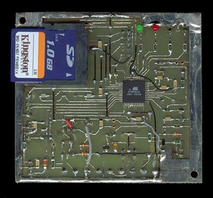
Second, I placed all through-hole parts on the (now trackless) copper-side, so they can be soldered to the pads lying on the same side as the SMT parts. I opted for through-hole version of all cumbersome components (like electrolytic capacitors and power regulators), in order to get a flat SMT side facilitating SD-card access.
I didn’t use special tools for etching: I printed a mirrored layout image on plain paper, and used it to expose pre-coated PCB material manufactured by Bungard, a German company. The light came from three standard-white, energy-saving lamps from IKEA. Exposure time was very long to balance for the use of non-transparent paper and the low amount of UV light produced by the lamps. Despite this rude setup, the board turned out well. After soldering and double checking every component, I was ready for applying power and programming the AVR.
BASCOM makes the porting from Mega128 code (used for the STK300) to the Mega32 (prototype) a trivial process. I merely selected the new target processor from IDE and changed the single line of code that used the second hardware UART of the ‘128, instructing the compiler to use a bit-bang implementation instead. Everything else is handled automatically by the compiler.
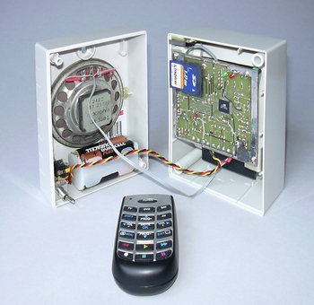
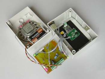
The PCB doesn’t hold all the parts. The camera and PIR sensor, among others, are placed on the enclosure box. I used breakable pin-strip headers for removable connections to the parts secured to the box. Use of coloured self-shrinking tubing, together with colour-encoded labels, helps preventing connection mistakes and gives the unit a tidy aspect.
The enclosure needs special care. The SD-card must be extracted without removing the PCB screws, so the PCB must protrude on top of the box walls. Also, the lid-switch must be placed in a way that it gets engaged when the box closes. I have modified a sturdy plastic box originally intended for holding electric switches (SCAME). I removed the DIN-Norm rail that was provided for switch holding on its bottom. I placed the loudspeaker in its place, drilling the holes for sound diffusion. Then I have positioned the lid-switch, and the supports for the PCB (cut from soft aluminium sheets), fixing them with extra-strong double-adhesive tape. The front panel consists of a cut-out of black plastic holding the camera, PIR sensor, remote control sensor and LEDs. It is secured to the front of the box with the same adhesive tape.
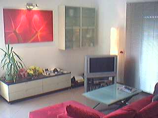
The finished prototype is aesthetically pleasant. Place it on your living room, the remote control next to it, to have a real piece of conversation for your next party.
Designers should never dare to say this, but yes, the Witnesscam is easy to use.
System setup requires you to copy the entire SPEECH folder to a blank SD-card. Then put the card in the camera, close the box, select an appropriate camera location and run the power cord from the wall-wart to the Witness camera. You are almost finished.
Once the camera is powered-up, it will greet you: “This is the Witness Camera recording system!” and give a readout of current settings (BRIEF key on the remote control replays it at any time).
The camera is immediately operating and taking pictures. The PIR LED fires each time a movement is detected. The RECORD LED fires when images are being recorded on the SD-card.
The first time, you need to set the clock.
- Take the remote control and press the CLOCK key until the camera asks for the password.
- Press keys 1-2-3-4 in sequence.
- The camera responds saying “OK”, followed by current date and time.
- Using the horizontal arrow keys ( ◄ and ► ) you can adjust the value of year, month, day, hour and minute. Use the vertical arrow keys ( ▲ and ▼ ) to move forth and back from years to months to days etc.
- Press OK or any other key to confirm the settings, and exit the voice menu.
The default setting is movement-triggered recording, taking 5 extra frames after the movement ends. If you want to change it:
- Press the MODE key on the remote control until the camera asks for the password.
- Press keys 1-2-3-4 in sequence
- The camera responds saying “OK”.
- Select the picture resolution (either standard or super), and recording mode (continuous recording, movement recording, interval timer recording, external trigger recording) using the arrow-keys as described above.
- If you selected a triggered recording mode, select the number of extra frames to take after the trigger cause (PIR sensor or external input) ended. If you selected the interval timer recording, specify the interval between snapshots (from 1 to 100 minutes).
You can check the pictures at any time without powering off the camera. As soon it detects that the case is being opened, the Witness camera stops recording. Likely, any pending disk operation is completed by the time you finish removing the lid. Anyway, have a look at the disk semaphore (green and red LEDs next to the card connector), and always wait for the green light before removing the SD-card.
Now the efforts for using standard media, file system and graphic formats start paying back. Gently insert the SD-card in your PC’s or laptop card reader. The icon of a removable SD-disk will be added to the system disk resources. You don’t need any additional software because Windows XP supports browsing JPG images folders by default. Click on the SD-disk and browse to the folder you want to analyze.
I designed the Witness Camera for home use, but its low-cost and flexibility make it a great starting point for many alternative applications.
Wherever a switch closure can be associated to an event, there is an opportunity for practical use: just route the switch to the external trigger input and you are done.
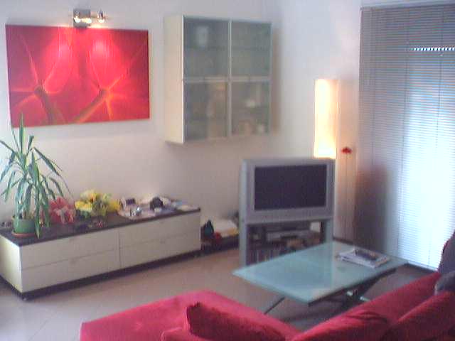
Next photo shows the ceiling view of my living-room captured by the Witness Camera. Your mileage can vary, but you should be able to get about 50,000 frames (resolution 320×240), or 25,000 (resolution 640×480), using a 1 GB card (I haven’t tried bigger cards). This corresponds to more than 40 hours of overall recording.Actual time span is much more than that. Likely, the best location for the camera is in the foyer, where people stand just a few minutes per day. In my case; just 20 minutes on average, giving an impressive 120 days of storage capacity.
| 640×480 | 320×240 |
 |
 |