Awhile back I published a simple design idea for a thermal airspeed sensor based on a self-heated Darlington transistor pair (Ref. 1). See Figure 1.
 |
|
| Figure 1. | Older design idea with self-heated Darlington thermal airflow sensor. |
In the circuit, Q1 plays the role of self-heated sensor. Its VBE tempco converts temperature into voltage which is then offset and scaled by A2 to a 5 V span. Meanwhile 200 mV reference A1 regulates Q1’s heating current to 0.2 V/R3 = 67 mA, for a constant power dissipation of 67 mA × 4.8 V = 320 mW. The resulting ambient vs junction temperature differential provides an airspeed readout as it’s cooled from a delta T above ambient of 64 °C at 0 fpm, down to 22 °C at 2000 fpm.
The resulting sensor is simple, sensitive, and solid-state, but suffers from a radically nonlinear airspeed response, as shown in Figure 2.
 |
|
| Figure 2. | VOUT versus airspeed response of thermal sensor is very nonlinear. |
An astute and helpful suggestion from reader Konstantin Kim resulted in the anti-log linearization VFC shown in Figure 3.
 |
|
| Figure 3. | Anti-log linearizing VFC. |
Figure 3 makes a useful improvement on linearity shown as Figure 4’s blue curve, but its lingering ~12% of FS error at mid-span is decidedly still far from perfect.
 |
|
| Figure 4. | Airspeed response linearity of Figure 3’s anti-log VFC is better but still un-terrific |
Veteran DI contributor Jordan Dimitrov noticed this shortcoming and provided an elegant computational numerical solution that virtually obliterates the problem and makes the net response all but perfectly linear, in his design idea (Ref. 2).
Nicely done, Mr. Dimitrov!
However, a consequence of performing linearization in the digital domain after analog-to-digital conversion instead of doing it in analog before conversion, is a significant increase in necessary ADC resolution, i.e., from 11 bits to 15.
Here’s why.
Acquisition of a linear 0 to 2000 fpm airspeed signal resolved to 1 fpm would require an ADC resolution of 1 in 2000 = 11 bits. But inspection of Figure 2’s curve reveals that, while the full-scale span of the airspeed signal is 5 V, the signal change associated with an airspeed increment of 1999 fpm to 2000 fpm is only 0.2 mV. Thus, to keep the former on scale while resolving the latter would require a minimum ADC resolution of 1 in 5/0.0002 = 1 in 25,000 = 14.6 bits.
15-bit (and higher resolution) ADCs are neither rare nor especially expensive, but they’re not usually integrated peripherals inside microcontrollers as mentioned in Mr. Dimitrov’s article. So, it seems plausible that a significant cost might be associated with provision of an ADC with resolution adequate for his design.
This prompted me to wonder whether a better performing analog linearization scheme might be feasible. If so and if not too complicated or costly to implement, it could provide an alternative to the digital solution with similar performance but without the need for a high resolution ADC. Turned out, it was. Figure 5 shows how.
 |
|
| Figure 5. | Adding one resistor (R6) and adjusting another (R1) ironed out the bump in Figure 3’s analog linearizing. |
Key to the linearity improvement is added resistor R6. It works by reducing the amplitude of the sawtooth timing waveform at the 555’s pin 2 by making it trigger early by an amount proportional to anti-log Q2’s collector current. This shortens VFC period and raises VFC frequency by a nonlinearity-correcting factor and results in Figure 6.
 |
|
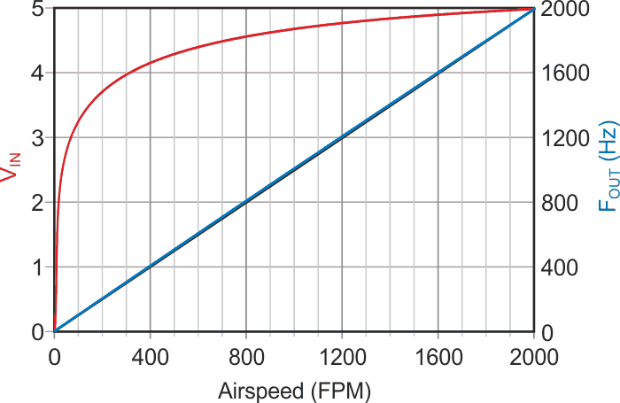
| Figure 6. | Improved analog linearity resulting from VFC modifications shown by overlaid blue and black lines. |
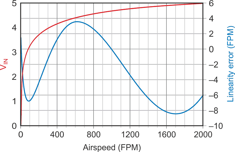
The resulting airspeed function deviates from perfect linearity by only –0.4% to +0.2% = –8 to +4 fpm as shown in Figure 6 and Figure 7 (expanded scale).
 |
|
| Figure 7. | Magnified residual linearity error shown in Figure 6. |
Admittedly this is certainly not as good as Mr. Dimitrov’s impressive post-conversion numerical result but is perhaps still acceptable for a simple analog solution. At any rate, as a practical matter, it’s better than any reasonable expectation for sensor accuracy, that the difference would seem of mostly academic interest only.
References
- Woodward, Stephen. "Nonlinearities of Darlington airflow sensor and VFC compensate each other."
- Dimitrov, Jordan. "Proper function linearizes a hot transistor anemometer with less than 0.2 % error."
