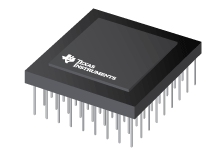
Datasheet Texas Instruments SM320C25GBM
| Manufacturer | Texas Instruments |
| Series | SMJ320C25 |
| Part Number | SM320C25GBM |

Digital Signal Processors 68-CPGA -55 to 125
Datasheets
SMJ320C25, SMJ320C25-50 Digital Signal Processors datasheet
PDF, 738 Kb, Revision: D, File published: Oct 31, 2001
Extract from the document
Prices
Status
| Lifecycle Status | Active (Recommended for new designs) |
| Manufacture's Sample Availability | No |
Packaging
| Pin | 68 |
| Package Type | GB |
| Industry STD Term | CPGA |
| JEDEC Code | S-CPGA-P |
| Package QTY | 1 |
| Carrier | JEDEC TRAY (5+1) |
| Device Marking | SM320C25GBM |
| Width (mm) | 24.38 |
| Length (mm) | 24.38 |
| Thickness (mm) | 2.03 |
| Pitch (mm) | 2.54 |
| Max Height (mm) | 3.62 |
| Mechanical Data | Download |
Parametrics
| Cycle Time | 100 ns |
| DMA | Ext Ch |
| Data / Program Memory Space | 64K/64K Words |
| Frequency | 40 MHz |
| MIPS | 10 |
| MOPS | 60 |
| Operating Temperature Range | -55 to 125 C |
| Package Group | CPGA |
| Pin/Package | 68CPGA, 68JLCC, 68LCCC |
| Rating | Military |
Eco Plan
| RoHS | See ti.com |
Application Notes
- Minimizing Quantization Effects Using the TMS320 DSP FamilyPDF, 268 Kb, File published: Jul 1, 1994
Due to its discrete nature DSPs represent variables and performs arithmetic functions with a finite word length. This produces three effects: the selection of filter transfer functions is quantized with filter poles and zeros existing only at specific locations in the z plane; the input is quantized; and noise is introduced from DSP multiplication and division operations. This document shows how - Engine Knock Detection Using Spectral Analysis With TMS320C25 or TMS320C30 DSPsPDF, 254 Kb, File published: Jan 1, 1995
An efficient method of detecting combustion engine knock is using spectral analysis. The detection process algorithm adapts to a no-knock reference at varying speeds and loads by using multiple frequencies. This document presents an problem overview current technology and two implementation examples are given to aid in the development of system specific hardware and software. The first system is - Setting Up TMS320 DSP Interrupts in 'C'PDF, 168 Kb, File published: Nov 1, 1994
Four steps are required to set the TMS320 DSP interrupts: create a interrupt service routine initialize the vector table and set the memory map enable the interrupts in the CPU and enable the interrupt sources. This document shows how to set the interrupts in C C callable assembly or in-line C. Sample C code segments are provided. The appendix gives complete examples for setting interrupt vec
Model Line
Series: SMJ320C25 (11)
Manufacturer's Classification
- Semiconductors > Processors > Digital Signal Processors > Other High Reliability DSPs
