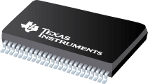
Datasheet Texas Instruments DS90CR217
| Manufacturer | Texas Instruments |
| Series | DS90CR217 |

+3.3V Rising Edge Data Strobe LVDS 21-Bit Channel Link Transmitter - 85 MHz
Datasheets
DS90CR217 +3.3V Rising Edge Data Strobe LVDS 21-Bit Channel Link - 85 MHz datasheet
PDF, 944 Kb, Revision: A, File published: Feb 19, 2013
Extract from the document
Status
| DS90CR217MTD | DS90CR217MTD/NOPB | DS90CR217MTDX/NOPB | |
|---|---|---|---|
| Lifecycle Status | NRND (Not recommended for new designs) | Active (Recommended for new designs) | Active (Recommended for new designs) |
| Manufacture's Sample Availability | Yes | No | No |
Packaging
| DS90CR217MTD | DS90CR217MTD/NOPB | DS90CR217MTDX/NOPB | |
|---|---|---|---|
| N | 1 | 2 | 3 |
| Pin | 48 | 48 | 48 |
| Package Type | DGG | DGG | DGG |
| Industry STD Term | TSSOP | TSSOP | TSSOP |
| JEDEC Code | R-PDSO-G | R-PDSO-G | R-PDSO-G |
| Package QTY | 38 | 38 | 1000 |
| Carrier | TUBE | TUBE | LARGE T&R |
| Device Marking | >B | DS90CR217MTD | DS90CR217MTD |
| Width (mm) | 6.1 | 6.1 | 6.1 |
| Length (mm) | 12.5 | 12.5 | 12.5 |
| Thickness (mm) | 1.15 | 1.15 | 1.15 |
| Pitch (mm) | .5 | .5 | .5 |
| Max Height (mm) | 1.2 | 1.2 | 1.2 |
| Mechanical Data | Download | Download | Download |
Parametrics
| Parameters / Models | DS90CR217MTD | DS90CR217MTD/NOPB | DS90CR217MTDX/NOPB |
|---|---|---|---|
| Clock Max, MHz | 85 | 85 | 85 |
| Clock Min, MHz | 20 | 20 | 20 |
| Compression Ratio | 21 to 3 | 21 to 3 | 21 to 3 |
| Data Throughput, Mbps | 1785 | 1785 | 1785 |
| ESD, kV | 7 | 7 | 7 |
| Function | Serializer | Serializer | Serializer |
| Input Compatibility | LVCMOS | LVCMOS | LVCMOS |
| Operating Temperature Range, C | -10 to 70 | -10 to 70 | -10 to 70 |
| Output Compatibility | LVDS | LVDS | LVDS |
| Package Group | TSSOP | TSSOP | TSSOP |
| Package Size: mm2:W x L, PKG | 48TSSOP: 101 mm2: 8.1 x 12.5(TSSOP) | 48TSSOP: 101 mm2: 8.1 x 12.5(TSSOP) | 48TSSOP: 101 mm2: 8.1 x 12.5(TSSOP) |
| Parallel Bus Width, bits | 21 | 21 | 21 |
| Protocols | Channel-Link I | Channel-Link I | Channel-Link I |
| Rating | Catalog | Catalog | Catalog |
| Supply Voltage(s), V | 3.3 | 3.3 | 3.3 |
Eco Plan
| DS90CR217MTD | DS90CR217MTD/NOPB | DS90CR217MTDX/NOPB | |
|---|---|---|---|
| RoHS | See ti.com | Compliant | Compliant |
Application Notes
- Improving the Robustness of Channel Link Designs with Channel Link II Ser/Des (Rev. A)PDF, 62 Kb, Revision: A, File published: Apr 26, 2013
This application note discusses how system designers are able to use Channel Link II ser/Des to improve old and new channel link designs. - CHANNEL LINK Moving and Shaping Information In Point-To-Point ApplicationsPDF, 269 Kb, File published: Oct 5, 1998
- Multi-Drop Channel-Link OperationPDF, 212 Kb, File published: Oct 4, 2004
- Receiver Skew Margin for Channel Link I and FPD Link I DevicesPDF, 418 Kb, File published: Jan 13, 2016
- AN-1108 Channel-Link PCB and Interconnect Design-In GuidelinesPDF, 245 Kb, File published: May 15, 2004
Application Note 1108 Channel-Link PCB and Interconnect Design-In Guidelines
Model Line
Series: DS90CR217 (3)
Manufacturer's Classification
- Semiconductors> Interface> Serializer, Deserializer> Channel Link I