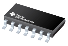
Datasheet Texas Instruments DS91C180TMAX/NOPB
| Manufacturer | Texas Instruments |
| Series | DS91C180 |
| Part Number | DS91C180TMAX/NOPB |

100 MHz M-LVDS Line Driver/Receiver Pair 14-SOIC -40 to 85
Datasheets
DS91D180/DS91C180 100 MHz M-LVDS Line Driver/Receiver Pair datasheet
PDF, 966 Kb, Revision: M, File published: Apr 18, 2013
Extract from the document
Prices
Status
| Lifecycle Status | Active (Recommended for new designs) |
| Manufacture's Sample Availability | No |
Packaging
| Pin | 14 | 14 |
| Package Type | D | D |
| Industry STD Term | SOIC | SOIC |
| JEDEC Code | R-PDSO-G | R-PDSO-G |
| Package QTY | 2500 | 2500 |
| Carrier | LARGE T&R | LARGE T&R |
| Device Marking | TMA | DS91C180 |
| Width (mm) | 3.91 | 3.91 |
| Length (mm) | 8.65 | 8.65 |
| Thickness (mm) | 1.58 | 1.58 |
| Pitch (mm) | 1.27 | 1.27 |
| Max Height (mm) | 1.75 | 1.75 |
| Mechanical Data | Download | Download |
Parametrics
| Device Type | Transceiver |
| ESD HBM | 5 kV |
| Function | Driver/Receiver |
| ICC(Max) | 29.5 mA |
| Input Signal | LVTTL,M-LVDS |
| No. of Rx | 1 |
| No. of Tx | 1 |
| Operating Temperature Range | -40 to 85 C |
| Output Signal | LVTTL,M-LVDS |
| Package Group | SOIC |
| Package Size: mm2:W x L | 14SOIC: 52 mm2: 6 x 8.65(SOIC) PKG |
| Protocols | M-LVDS |
| Signaling Rate | 200 Mbps |
Eco Plan
| RoHS | Compliant |
Application Notes
- Designing an ATCA Compliant M-LVDS Clock Distribution Network (Rev. B)PDF, 276 Kb, Revision: B, File published: Apr 26, 2013
This application report provides a guide to designing ATCA compliant clock distribution networks using M-LVDS devices. The application report consists of a quick description of an ATCA synchronization clock interface, an overview of M-LVDS standard, an extensive discussion on performance of M-LVDS devices in an ATCA backplane and a set of design recommendations and rules that will assist you in bu
Model Line
Series: DS91C180 (2)
- DS91C180TMA/NOPB DS91C180TMAX/NOPB
Manufacturer's Classification
- Semiconductors > Interface > LVDS/M-LVDS/PECL > Buffers, Drivers/Receivers and Cross-Points
