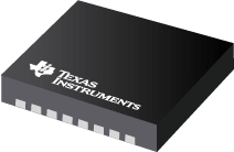
Datasheet Texas Instruments LDC1000NHRR
| Manufacturer | Texas Instruments |
| Series | LDC1000 |
| Part Number | LDC1000NHRR |

5V, High Resolution, Inductance to Digital Converter for Inductive Sensing Applications 16-WSON -40 to 125
Datasheets
LDC1000 Inductance-to-Digital Converter datasheet
PDF, 3.8 Mb, Revision: C, File published: Sep 10, 2015
Extract from the document
Prices
Status
| Lifecycle Status | Active (Recommended for new designs) |
| Manufacture's Sample Availability | Yes |
Packaging
| Pin | 16 |
| Package Type | NHR |
| Industry STD Term | WSON |
| JEDEC Code | R-PDSO-N |
| Package QTY | 1000 |
| Carrier | LARGE T&R |
| Device Marking | LDC1000 |
| Width (mm) | 4 |
| Length (mm) | 5 |
| Thickness (mm) | .8 |
| Pitch (mm) | .5 |
| Max Height (mm) | .8 |
| Mechanical Data | Download |
Eco Plan
| RoHS | Compliant |
Design Kits & Evaluation Modules
- Evaluation Modules & Boards: LDC1000EVM
LDC1000EVM - Evaluation Module for Inductance to Digital Converter with Sample PCB Coil
Lifecycle Status: Active (Recommended for new designs)
Application Notes
- Interfacing LDC1000 with the MSP430 LaunchPadPDF, 708 Kb, File published: Oct 17, 2013
The LDC1000 is a programmable inductance-to-digital converter for use in inductance-sensingapplications. It offers a complete signal path solution between an LC tank and a microcontroller byproviding proximity and inductance data. The MSP430 is an ideal microcontroller solution for low-cost,low-power precision sensor applications because it consumes very little power. This library provides - LDC1000 Temperature CompensationPDF, 308 Kb, File published: Sep 12, 2013
LDC1000 is a high-precision Inductance-to-Digital converter with internal precision of 0.1% over dynamicrange. However, other factors may influence measurement precision greatly, dominating the systemperformance. One of these is temperature variation.This App-note will discuss the physical effects of temperature variation on inductive sensing and providemethods to mitigate these effects. - Performing L Measurements from LDC DRDY TimingPDF, 66 Kb, File published: Nov 6, 2015
TI’s LDC1000 and LDC1101 devices measure the resonant frequency of an LC tank to determine the inductance of a sensor. Some applications require higher measurement resolution than the LDC1000 or even LDC1101 can provide. With proper configuration of the LDC, an external time measurement device can be used for improved inductance measurement resolution. - Using Multiple Sensors With LDC1000PDF, 74 Kb, File published: Mar 2, 2015
- Configuring Inductive-to-Digital-Converters for Parallel Resistance (RP) Variati (Rev. A)PDF, 255 Kb, Revision: A, File published: Jun 1, 2015
This application note reviews sensor RP configuration for LDC devices. LDC1000, LDC1041, LDC1051, LDC1312, LDC1314, LDC1612, LDC1614 are covered in this note. Clear understanding on how to set the RP_MIN and RP_MAX registers is necessary for not only RP measurements, but also for optimum L measurements. The fundamental principle of RP measurements is that magnetic fields from an LC circuit ge - LDC Device Selection Guide (Rev. B)PDF, 360 Kb, Revision: B, File published: Mar 21, 2017
- LDC Sensor DesignPDF, 1.0 Mb, File published: Mar 24, 2015
Getting the best performance out of an LDC requires a sensor suitable for the measurement. This app-note covers the parameters to consider when designing a sensor for a specific application. Specific areas of focus include the physical routing characteristics of PCB based sensors, considerations for the sensor capacitor, and techniques to minimize or compensate for parasitic effects. - LDC1xxx LDC Target Design (Rev. A)PDF, 907 Kb, Revision: A, File published: May 9, 2017
Texas Instruments’ Inductive-to-Digital Converter (LDC) technology can accurately measure with a wide variety of target sizes, shapes, and material composition. There are several target design guidelines to maximize the effectiveness of an LDC measurement system. This application note covers the relevant factors of target design that affect inductive sensing, and provides guide - Measuring Rp of an L-C Sensor for Inductive SensingPDF, 205 Kb, File published: Oct 1, 2015
When designing an application using TI’s LDC series of inductive sensors, it is necessary to know the L-C sensor’s equivalent parallel resistance RP at the sensor’s resonant frequency. The RP value changes as the target is moved; the minimum RP occurs when the metal target is closest to the sensor. The maximum RP occurs when the target is at the farthest distance. Accordingly, both values should b
Model Line
Series: LDC1000 (3)
- LDC1000NHRJ LDC1000NHRR LDC1000NHRT
Manufacturer's Classification
- Semiconductors > Sensing Products > Inductive Sensing > Inductance to Digital Converters
