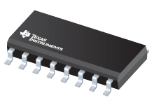
Datasheet Texas Instruments ULN2004ADR
| Manufacturer | Texas Instruments |
| Series | ULN2004A |
| Part Number | ULN2004ADR |

High-Voltage, High-Current Darlington Transistor Array 16-SOIC -20 to 70
Datasheets
ULN200x, ULQ200x High-Voltage, High-Current Darlington Transistor Arrays datasheet
PDF, 1.3 Mb, Revision: O, File published: Jan 22, 2016
Extract from the document
Prices
Status
| Lifecycle Status | Active (Recommended for new designs) |
| Manufacture's Sample Availability | No |
Packaging
| Pin | 16 |
| Package Type | D |
| Industry STD Term | SOIC |
| JEDEC Code | R-PDSO-G |
| Package QTY | 2500 |
| Carrier | LARGE T&R |
| Device Marking | ULN2004A |
| Width (mm) | 3.91 |
| Length (mm) | 9.9 |
| Thickness (mm) | 1.58 |
| Pitch (mm) | 1.27 |
| Max Height (mm) | 1.75 |
| Mechanical Data | Download |
Parametrics
| Delay Time(Typ) | 250 ns |
| Drivers Per Package | 7 |
| Input Compatibility | CMOS |
| Iout/ch(Max) | 500 mA |
| Iout_off(Typ) | 50 uA |
| Output Voltage(Max) | 50 V |
| Package Group | SOIC |
| Package Size: mm2:W x L | 16SOIC: 59 mm2: 6 x 9.9(SOIC) PKG |
| Peak Output Current | 500 mA |
| Rating | Catalog |
| Switching Voltage(Max) | 50 V |
| Vol@Lowest Spec Current(Typ) | 900 mV |
Eco Plan
| RoHS | Compliant |
Application Notes
- Improved Thermal Dissipation and Energy Efficiency for Peripheral DrivingPDF, 330 Kb, File published: Oct 30, 2014
- Wave Solder Exposure of SMT PackagesPDF, 206 Kb, File published: Sep 9, 2008
It is common practice to attach surface mount components to the underside of a printed circuit board (PCB) by processing the PCB through a wave soldering operation after gluing the components to the PCB. This paper ummarizes results of several tests performed to understand the performance of surface mount components when exposed to the conditions outlined in JESD22A111. - Stepper Motor Driving with Peripheral Drivers (Rev. A)PDF, 172 Kb, Revision: A, File published: Dec 2, 2016
This application report describes in detail how to interface stepper motors with TI peripheral drivers. Primarily, this report discusses how to connect and drive stepper motors, including the stepper motor driving patterns. Advantages and disadvantages to each stepping pattern are discussed; and logic tables, timing diagrams, and pictorial representations of each driving pattern are provided.
Model Line
Series: ULN2004A (9)
Manufacturer's Classification
- Semiconductors > Power Management > Peripheral Driver and Actuator
