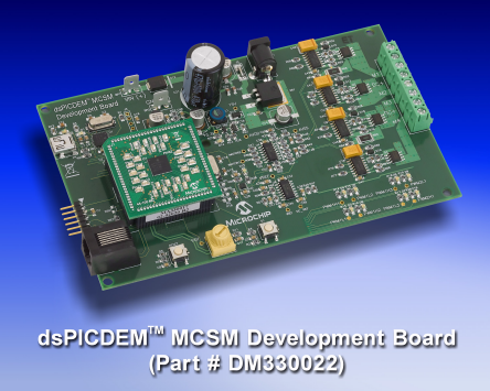
Development Board Microchip dsPICDEM MCSM (DM330022)
The Microchip dsPICDEM MCSM Development Board is targeted to control both unipolar and bipolar stepper motors in open-loop or closed-loop (current control) mode.
Detailed Description
The hardware is designed in such a way that no hardware changes are necessary for 8-, 6- or 4-wire stepper motors in either bipolar or unipolar configurations. Software to run motors in open-loop or closed-loop with full or variable micro-stepping is provided. A GUI for controlling step commands, motor parameter input, and operation modes is included. This flexible and cost-effective board can be configured in different ways for use with Microchip’s specialized dsPIC33F Motor Control Digital Signal Controllers (DSCs). The dsPICDEM MCSM Development Board offers a mounting option to connect either a 28-pin SOIC device or a generic 100-pin Plug-In Module (PIM). A dsPIC33FJ32MC204 DSC PIM (MA330017) is included.
The dsPICDEM MCSM Development Board supports terminal voltages up to 80V and currents up to 3A. The dsPIC33F device uses the MOSFET driver to drive the two full-bridge inverters that power the motor windings. The board includes various circuitries to perform the following functions:
- Drive two motor windings with the two on-board full-bridge inverters
- Measure feedback and other analog signals (i.e., current, DC voltage, Potentiometer and Fault signals)
- Communicate with a host computer or an external device via USB
The dsPIC DSC devices feature an 8-channel, high-speed PWM with Complementary mode output, a programmable ADC trigger on the PWM reload cycle, digital dead time control, internal shoot-through protection and hardware fault shutdown. These features make the dsPIC DSC an ideal solution for high-performance stepper motor control applications where control of the full-bridge inverter is required.
The MCSM Development Board is available in two configurations:
- dsPICDEM MCSM Development Board : DM330022
- dsPICDEM MCSM Development Board Kit : DV330021
Key Features:
- Motor control interfaces:
- Two full-bridge inverters
- Two phase current sense resistors
- DC bus voltage sense resistor
- Over-current protection
- Built-in power supplies:
- 15V power supply, maximum power available 11 W
- 3.3V power supply, maximum power available 2 W
- Power supply connectors:
- 24V power input connector (J6) for the controller and power stage
- Auxiliary Power Tab Fast-On connectors (BP1 and BP2) for the power stage
- Motor control device (U2) socket:
- The dsPIC33FJ12MC202 Motor Control device in SOIC package (U3) footprint
- User Interfaces:
- One push button (S1)
- Reset push button (RESET)
- 10K Ohm Potentiometer (POT)
- LED indicators for PWM outputs arranged in a full-bridge format
- LED indicator for over current
- Communication Ports:
- UART communication via USB (J4)
- Programming Connectors:
- ICSP connector for programming a dsPIC DSC device (J2)
- RJ11 connector for programming a dsPIC DSC device (J1)
- ICSP connector for programming the PIC18LF2450 USB-to-UART Bridge (J3)
