EAGLE users have long asked for a simple 3D export that would allow them to cross their designs from the electrical realm into the mechanical realm. The current crop of solutions have suffered from either limited applicability or generated a format that wasn't widely accepted among mechanical CAD tools. The purpose of this blog post is to inform users of a new tool that can finally fulfill this long requested need.
CadSoft has partnered with SimplifiedSolutions Inc. to create the IDF-to-3D tool.
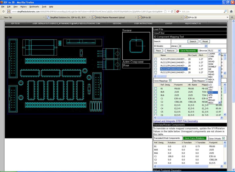 |
| IDF-to-3D interface |
This tool allows users to export IDF files from EAGLE which they can then import into their MCAD tool of choice for further improvement. IDF files are a first-order 3D model, all components are represented as cubes whose dimensions represent the maximum dimensions of the components on the PCB. For simple cases this might be enough, however, in the general use case the end user would prefer to replace these cubes with more accurate 3D models.
Users can choose to make this replacement manually in their MCAD tool or use the SimplifiedSolutions web interface to do the work for them. The online tool has a large library of vetted 3D models that are already mapped to EAGLE's built-in libraries, so many of your components will be automatically mapped once you upload the file. Any remaining components that aren't mapped can be mapped by users through the intuitive and easy to use interface. Users can also upload their own models and create their own library of preferred models.
The online tool can export 3D PDF, STEP, and STL formats. The PDF can be used as a simple visualization and for documentation purposes. The STEP file is workhorse file format for mechanical CAD tools. Almost all standard mechanical tools can import STEP files, which would allow the end user to make accurate measurements of the model and use it for real design work. The STL format allows 3D printers to print out a physical representation of your board, which can then be used to check enclosure clearances before your board is actually made. This can help speed up design iterations and avoid costly mistakes.
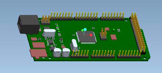 |
| Partially mapped ArduinoMEGA. Unmapped components appear as brown rectangles. |
Using the tool is as simple as running the EagleIDFExporter.ulp that comes with EAGLE. The ULP extracts the X and Y dimensions from the EAGLE packages, the Z dimension can be defined by creating a HEIGHT attribute for components whose value is the Z dimension of the component in millimeters. If no height is defined, then the ULP assumes a height of 1mm. If you intend to use the IDF model only, then it's in your interest to define a HEIGHT attribute. If you will be converting to a STEP file or replacing the cubes yourself then there's no need to create this attribute.
The ULP will generate two files: an emn and an emp file which are then uploaded to the IDF-to-3D web interface. From there the IDF-to-3D tool will automatically map any parts it can and allow you to finish mapping any it was unable to do. Now you are ready to export your output of choice 3D PDF, STEP, or STL.
This new tool will give you unlimited use for three years for $300.00. The 3D PDF is always available for evaluation and non-paid users. If you find yourself needing 3D export from EAGLE this tool will allow you to bridge the mechanical and electrical worlds, simplifying your design integration and helping you get your product to market faster. Finally there is an easy, affordable way to get quality 3D export from EAGLE.
