Relays are common electromechanical devices in electrical circuits that come in two types: either latched or non-latched. Latched relays retain their last switch position even after complete power loss and are available in either single coil or dual coil versions. The single-coil latched relay uses only one coil to set or reset the switch position, but requires positive and negative voltage. When positive voltage is applied, current flows in one direction and enters the relay into the set-state (i.e. relay switch closed). A negative voltage reverses the current direction, placing the relay into the reset-state (i.e. switch opened).
Dual-coil latched relays, on the other hand, use only positive voltage but require two power sources or drivers. Such relays have a set-coil and a reset-coil. When the set-coil is energized, the relay enters the set-state. Conversely, when the reset coil is energized, the relay enters the reset-state. The two coils are never energized at the same time.
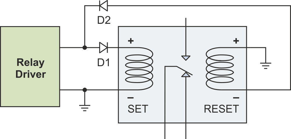
If you wish to use a dual-coil relay, but the only driver you have available is for a single-coil relay, there is an easy way to convert that single-coil driver handle the two-coil relay, shown in Figure 1. This conversion to positive-only drive is particularly useful for relay testing, because you need only one voltage polarity instead of two. This reduction can significantly simplify the relay testing setup.
 |
|
| Figure 1. | Diodes convert a single-coil relay driver to dual-coil use. |
The operation is simple. When the coil driver output voltage is positive, current flow through diode D1 to energize the set-coil, while the reset-coil is unpowered because D2 blocks the current. The relay enters the set-state. When the voltage is negative, diode D1 blocks the current flow through the set-coil and diode D2 energizes the reset-coil.
The latched relay in Figure 1 has two independent coil connections using 4 pins. Some dual-coil relays, however, use only three pins with a common coil connection as shown in Figure 2. This configuration needs a slightly more complicated configuration, involving four diodes.
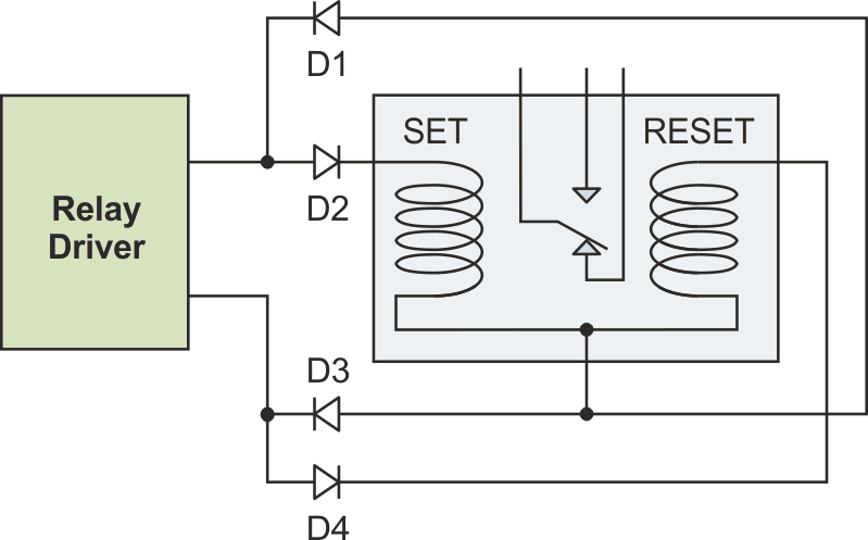 |
|
| Figure 2. | Four diodes are needed to convert the single-coil signal for dual coil use when the coils share a common connection. |
As before, when the driver voltage is positive, current is flowing through diode D2, the set-coil, and D3. Diodes D1 and D4 are reverse biased, blocking the current to the reset-coil. Similarly, when the voltage is negative current flows through the diode D4, the reset-coil, and D1, while the set-coil is de-energized. Again only one coil is on at a time.
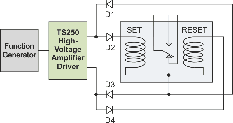
The conversion circuit has the additional benefit that it makes things easier when testing dual-coil relays for their AC performance characteristics, such as operate-time (turn-on time), bounce-time, break-time, and maximum frequency. Just replace the relay driver with a square-wave voltage signal generator. Because many relay coils require high voltage, up to 48 V, and high current anywhere from 20 mA to over 1000 mA in some cases, a signal generator alone may not be enough. In such cases a high-voltage function generator amplifier, such as the TS250 from Accel Instruments, is needed to boost the voltage and current (Figure 3).
 |
|
| Figure 3. | Testing the dual-coil relay using only one function generator and a high- voltage driver. |
The diode circuits provide an easy way to convert single-coil relay drive signals to dual-coil use. This approach gives system designers the option of using either singe-coil or dual-coil latched relays without needing to change the driver. Furthermore it enables dual-coil latch relay testing with just one signal driver.
